SAFETY CRITERIA
1 Attention: before beginning anykind of procedure of installation is LOCKED ACTUATOR
absolutely necessary to read all this manuall. The gear motor may with trasmission and drive lever be either locked.
2 Test/Control that the perfornces of the actuator auswer to your The electric lock must be installed on the wing that opens first and must be
installation needs. connected with the terminal board of the control unit.
3 Besides control that: Position of the electric lock: (Fig. C).
• The gare hinges are in good conditions and perfectly fattened. Position 1: Lock between the wings.
• The gate has mechanicall stops in the opening and the closing. (in this case is necessary to use the bolt RT15 on the second wing)
Position 2: Lock in the floor.
INSTALLATION ADVICE (in this case the utilisation of the bolt is not essential)
Connections: In any other case, we suggest the locked actuator.
• See the “Operational Diagram” and refer to the control central scheme. In this case remenber to remove the lock or at least block the lock in opening
• The adjustment must be effected when the device has no power supply. position and take away all the bolts of lock.
• Foresee a omnipolar breaking device near to the apparatus (the contact
must measure at least 3 mm). DETERMINATION OF FIXING MEASURES
Always protect the power supply using a 6A automatic switch, or a 16A Following the instructions, choose the exact position of the gear motor
single-phase switch fises. paying attention to the structure and the opening you want.
• The power supply lines the motors, to the control unit and the connection GATE FIXED IN THE MIDDLE OF THE PILLAR (FIG. A)
lines to the outfits must be sepated to avoid troubles which could In this case the maximal opening corner of the gate is 90°.
generate problems in the installation working. GATE FIXED ON THE EDGE PILLAR (FIG. B)
• Any outfits (of control or safety) eventually connected to the control unit In this case the gate can open with a corner superior to 90°. (max 110°)
must be tension free.
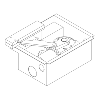
Spare parts: PROTECTION BOX (FIG. D)
• use esclusively original spare parts. - Make, in the established position, a digging on the ground which can
Installation: cobtain the Protection box.
• In order to correctly use the product and to exclude the possibility of - Put the Protection box into the digging.
injury or damage, refer to the "Generals" page enclosure, which is an Make sure that the pin is aligned with the pivot of the leaf and that you
integrated part of this manual. have respected the distance of 65 mm between the centre of the pivot
• The use of this equipment must be in observance of the safety standards and the piller. (Fig. E)
in force in the country where it is installed, as well as the standards - Make near the holes F1 of the Protection box a discharge for the water
governing proper installation. in order to avoid a possible back water as well as an oxidation of the gear
Warranty: motor. (Fig. F)
• The warranty supplied by the manufacturer becomes void in the event of - Notioe that the electrical cables have to go through the hole F2 of the
interference, carelessness, improper use, lightening damage, power Protection box, as in the “Functional scheme for swing gate”. (Fig. N)
surges or use by unqualified personnel. - Make sure that the Protection box is perfectly horizontal and bury it with
• The warranty will also become void in the event of the following: concrete.
Failure to observe the instructions given in the manuals supplied with the
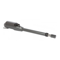
product. GEAR MOTOR
The application of any part in a manner differing from that provided for - Put the gear motor on the bottom of the Protection box and fasten it
current legislation or the use of spare parts which are unsuitable and/or firmly to the tapping-screw with the right nuts M12. (Fig. F)
not approved by manifacturer. - Install the lever “L1” on the pin which comes out from the box. (Fig. G)
• The manufacturer cannot be held responsible for damages due to - Install the lever ”L2” lever of Transmission on the “L1” ( just installed).
improper or unreasonable use. (Fig. H)
- Juin the lever “L2” to the lever “L3” (coming out from the gear motor) by
INSTALLATION INSTRUCTION SEQUENCE driving thepins into the right pivots and them with screws SPEI M6X18.
1 Before the installation, anomalyse the risks referring to the chapter (Fig. H)
“Generalities” of this instructions manual, fill the technic table and - Closed the Protection box, with the cover and fasten it with the right
eliminate the risks a noticed. screw M6x18 TPSCEI.
In case of more risks, foresee the installation with security system. - Aligne both the leaf of the gate and the lever “L1” which comes out from
2 Est the security laws of the “Security Criteria”. the Protection box. Fix them all with soldering.
3 Control all the components.
4 Decide the position where you want to install the gear motor. MECHANICAL STOP
5 After deciding the right position tou have to make a digging on the Now it is necessary to put the locks in order to make the openin and in the
Ground. closing of the swing.
6 Install the Protection box in the digging on the Ground.
7 Foresee a discharge for the water. GATE WITH EXTERNAL OPENING
8 Connect the Electrical cables as in the “Operational Diagram” If the gate has an external opening it is possible to put the motor in to the
9 Put the gear motor on the botton of the Box and fasten it firmly inside the Protection box moving it of 180°.
protection.
10 Install the levers for the gate movement MOTOR RELEASE
11 Close the Protection box. - Turn off the electricity.
12 Aligne and fix the leaf of the gate. - Put the release key in the correct hole on the release lever and turn the left
13 Connect the central and all the accessoires clockwise, whereas the right leaf in the other direction.
14 Program the radio receptor In this way you will release the transmission. (Fig. I)
15 Pèrogram working times Take out the key and do the emergency manouvre.
In case of badworking, see the “Anomalies and Counsuls” - Now it is possible to open and to close the gate handly.
IF YOU DO NOT FIND ANY SLUTION COLL THE NEATEST ASSISTENCE - In order to re-estabilish the transmission, you have to put the leaf in the
CENTRE. starting position (the clutch is auomatic).
- Re-estabilish the power supply.
DEVICE 180° (A 008)
The device has been applied to particular cases, to allow openings util 180°.
For a correct installation of the device 180°, fallow carefully these
instructions:
- Find out the pinion P1 on the gear motor. (Fig. L)
- Mount the lever with pinion P2 on the pin which comes out from the box.
- put the transmission key “C” on the spur wheel, stretch it and fasten it.
- Grease the chain. Close the box with the cover and fix it with suitable
screws M6x18 TPSCEI.
- Aligne both the leaf of the gate and the lever L1 which comes out from the
box. Fix them all with soldering.
- Repeat the same operation with the other leaf.
 Loading...