14
15
W W W . D Y E P A I N T B A L L . C O M W W W . D Y E P A I N T B A L L . C O M
The RIZE RIZE
RIZE
RIZE
RIZE
RIZE
RIZE RIZE
RIZE
RIZE
RIZE
RIZE
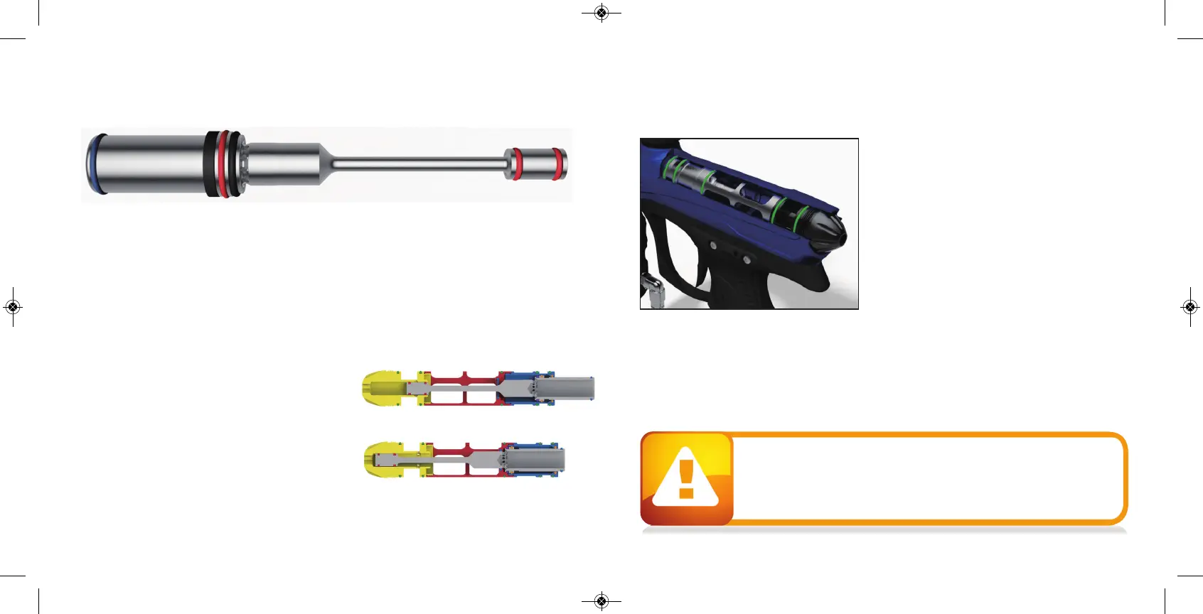
™ BOLT is the main component o f the ™ marker. In ord er to achieve the b est
possible p erformance of the RA IL™ it is essential that the ™ BOLT is kept clean, well lub ed
and in good working order.
The ™ BOLT should b e cleaned and re- lubed after each d ay of use.
There are 4 p arts in the ™ BOLT kit that mount together as one unit. To remove the ™
BOLT from yo ur ™, use a 1/ 4 "
allen key and turn
the Back Cap out 2 full turns co unter
clockwise. Now p ull o ut the comp lete RA IL™ b olt kit from the ™.
To dis- assemble the ™ BOLT kit you unthread the front most p art called the Can and the
Manifold from each other. Then p ull out the actual moving bolt from insid e these p ieces. Notice
that to sep arate the Can and the Bolt you need to remove
the b olt tip O- ring before the b olt
is able to slid e throug h
the C
an.
HOW DOES IT WORK
A ir is sup plied into two po ints on the ™ BOLT. In the
back air is routed through the Back Cap and Manifold
and fills up the sup ply chamb er around the Manifold . In
the front air is routed through the solenoid into the Can.
This air p ushes against the Sail o n the Bolt, which keep s
the b olt in the back p ositio n.
FORWARD POSITION
RIZE
™
BO LT
ASSEMBLY A ND MAI NTENA NC E
RIZE
™
BO LT
ASSEMBLY A ND MAI NTENA NC E
When the ™ is fired the solenoid is actuated
and the air insid e the Can is exhausted out. The
force created by the air insid e the supp ly chamb er
causes the b olt to start moving forward . Once the
bolt has moved ab out half way forward , the tail of
the b olt closes the inp ut into the supp ly chamb er.
Once the Bolt reaches the forward p oint, the valve
of the ™ B
olt is opened and air inside the
supply chamber g o
es throug h the Bolt and fires
the p aintball. After this the solenoid is d e-
activated and g as is sup plied through the
solenoid b ack into the Can. This causes the Bolt
to return to the b ack position and the sup ply
chamb er to be re- charg ed.
When servicing your marker:
• Make sure your hopper is removed from the marker.
• Make sure there are no paintballs in the breech of the marker.
• Always remove the air supply and relieve all gas pressure in the marker
before disassembly.
• When using the marker in temperatures below 50° Fahrenheit it may be
necessary to lube the RAIL™ bolt more frequently.
BACK POSITION