04
05
W W W . D Y E P A I N T B A L L . C O M W W W . D Y E P A I N T B A L L . C O M
QUICK START UP GUIDE
Before playing with your new RIZE ™ paintball marker there are a few
important steps to take.
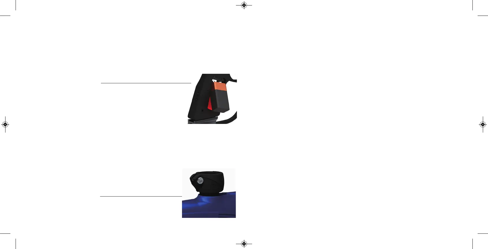
STEP 1. BATTERY INSTALLATION
A . Remove three right hand sid e g rip p anel screws with a 3/ 32” allen key.
B. Open grip panel and install 9V battery into the connector inside the frame. Start
by inserting the top of the battery into the recess and aligning the battery terminals
with the contacts on
the board, then pushing the bottom of the battery fully into
place. Ensure that the battery removal ribbon leaves a small tail accessible from
under battery when installed to aid for easy battery removal. Note the markings
above the battery housing which indicate which of the board contacts are positive
and negative and install the battery accordingly.
C. Close g rip p anel and tig hten the three screws
back. While closing the p anel
ob serve that no wires g et caug ht b etween the frame and the grip p anel.
STEP 2. BARREL INSTALLATION
A . Screw on the b arrel to the front of the RIZE ™. Make sure it thread s all the
way in and is secure.
B. Attach the b arrel p lug so that it covers the tip of the b arrel and secure
the g un.
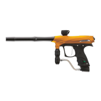
STEP 3. LOADER INSTALLATION
STEP 4 . ATTACHING GAS SOURCE
Screw on a preset air system into the
airport located on the b ottom o f the g rip
frame.
Be sure the air system is screwed in all the way into the A irp ort. If there is a leak
from the airport when screwing in the air system, rep lace the o - ring on the preset
reg ulator.
STEP 5. TURNING ON THE RAIL™ AND CHECKING THE VELOCITY
A . Make sure you and everyb od y aro und yo u is wearing A ST M / CE ap proved
paintball masks.
B. Press and hold the top b utton
lo cated b ehind the g rip frame until the RA IL™
turns on.
WARNING, THE RAIL™ IS LIVE. MAKE SURE BARREL PLUG IS IN PLACE
AND DO NOT POINT THE RAIL™ AT ANYTHING YOU DON’T INTEND TO SHOOT.
C. F ill up the lo ader with .68 calib er p aintballs.
D. Sho ot the RA IL™ over a chro nograp h to check the velo city. If ad justment is
need ed, ad just the velocity by turning the Hyper3™ velocity ad justment screw with
a 3/ 16” al
len key. In ( clockwise) will red uce the velo city and out ( counter clo ckwise)
will increase the velocity. After each adjustment it takes a few sho ts b efore the
chang e can b e seen o n the chronog rap h. Never ad just the RA IL™ to sho ot faster
than 30 0 fp s or what the field rules / local laws permit.
Q UI CK REF ERENC E
USI NG YO UR MA RK ER
Q UI CK REF ERENC E
USI NG YO UR MA RK ER
Tighten your loader into the adjustable feedneck using a 5/32” Allen key.
For best performance, use a force feeding motorized loader,
preferably the Rotor™ Loader.