12
13
W W W . D Y E P A I N T B A L L . C O M W W W . D Y E P A I N T B A L L . C O M
TRI GGER
ADJUSTMENT
RIZE
™
BOARD
SE TTINGS AND F UNC TI ONS
BATTERY
The 9V b attery will last fo r ab out 12,0 0 0 sho ts. Please b e aware that there are sub stantial
differences in p erformance b etween d ifferent b rand s o f b atteries. Use of hig h q uality alkaline or
lithium io n batteries is recommend ed fo r maximum b attery life. If you p lan not to use your marker
for a long p eriod o
f time ( a month) , it is reco mmend ed that you remove the b attery fro m the
marker. W hen the b attery vo ltag e starts to g o too low, the marker will not fire with every trig ger
pull. For to urnament use, it is recommend ed to chang e the b attery for each to urnament.
CHANGING THE BATTERY
The b attery is ho used on the rig ht sid e of the g rip frame. To access the b attery, remove the three
screws holding the rig h
t side grip panel d own. Use a 3⁄32” allen key. When inserting a new b attery
notice the + and - marks on the board. The p ositive lead of the 9V battery g oes to the left and the
neg ative lead to the rig ht.
NOTE: If the marker will not function with the eye on, there is a good chance the battery needs
to be changed.
• A low battery will not b e able to power b oth the ACE eye and the trigg er
switch, causing
ACE eye failure.
• If the b attery is low, the marker will not fire with every trig ger p ull.
• Be sure the trig ger is not adjusted to the point where it is too sensitive
and may cause accid ental d ischarge of the marker.
• Removing the trigg er sp ring will cause premature wear on the microswitch,
resulting in failure.
• Be sure you do not pinch the wires between the frame and body when
reattaching the frame to the body.
ADJUSTING YOUR TRIGGER
The Trig ger ’s forward travel and over travel are fully
adjustable so that the user can fine- tune the trig ger to
his/ her exact p reference.
To ad just the trig ger an .0 50 ” and 5/ 64 ’ Allen key is
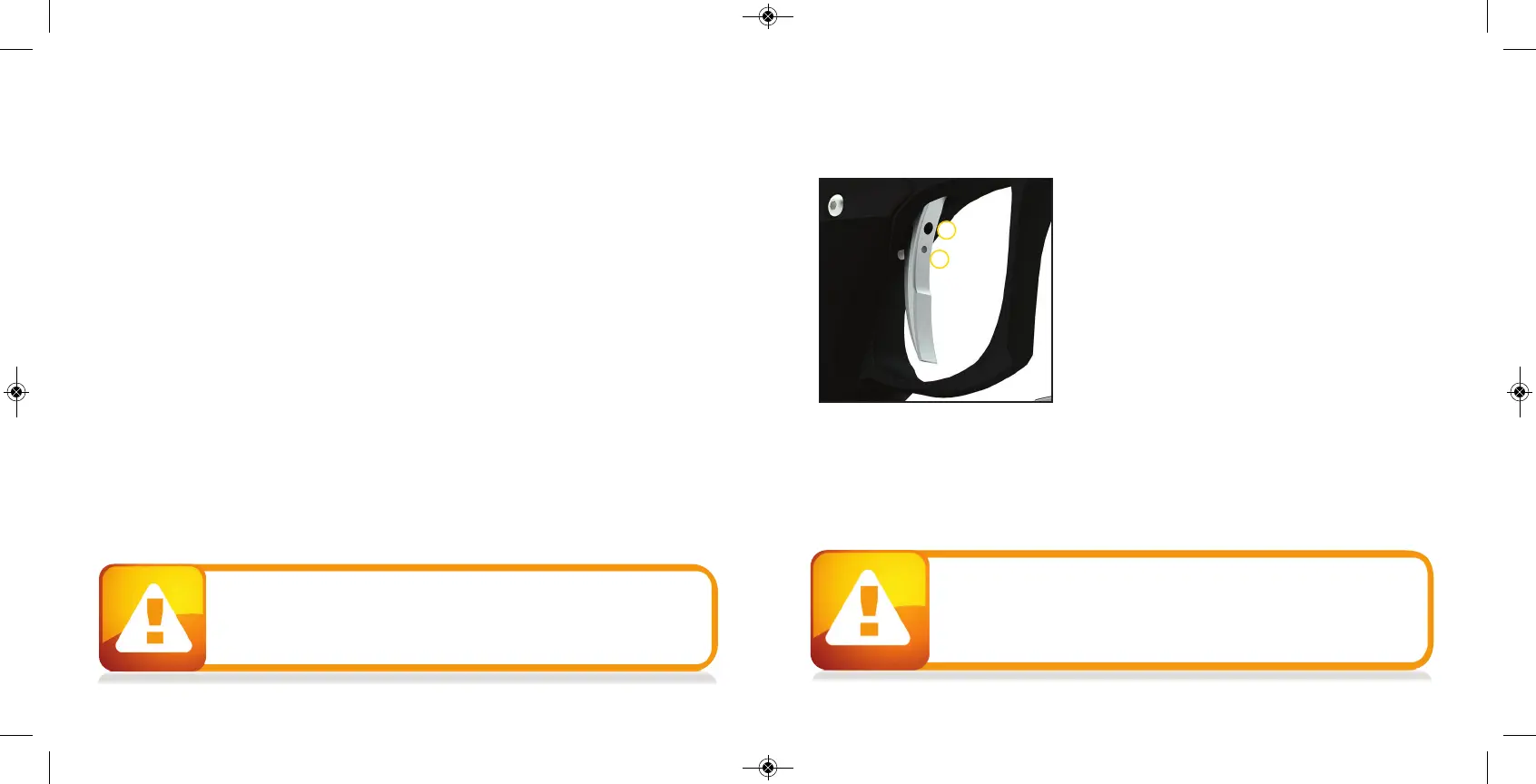
need ed. There are two ad justment screws lo cated on the
trigg er.
The upp er screw on the front o f the trig ger co ntro ls the
forward travel ( 1) and req uires a 5/ 64 ” allen wrench to
adjust. Screwin
g it in will incease the trig ger ’s leng th o f
pull. Note: If this screw is screwed too far out, the switch
will b e d ep ressed all the time causing the RIZE ™ to fire
once immed iately after turning it on and not firing after that! ( Fig . 1) .
The lower screw on the front o f the trig ger co ntro ls the over travel ( 2) and req uires the .0 50 ” allen
wrench to ad just. By turning this screw you can ad just how far b ack t
he trig ger will travel. Note: If
this screw is adjusted too far, the trig ger will no t b e allowed to travel far enough to d ep ress the
switch and the marker will no t fire.
The trig ger spring used to return the trig ger is located insid e the frame. It is not sug gested to
remove this spring as it will cause excess wear on the microswitch and cause trig ger bounce.
1
2
FIGURE 1