The machine is also equipped with a vacuum-cleaner
adapter to help you work in a dust-free environment.
We recommend only to use original PROXXON spare
parts and saw blades.
5.3. Specifications
Nominal voltage:110-120V AC, 60 Hz
Power:
1
/ 8 hp (85 Watts)
Band speed:395 to 820 ft/min, infinitely
variable
Noise level:<70 dB (A)
Weight:15.5 lb (7 kg)
Dimensions:
Work table:7
7
/ 8 " x 7
21
/ 32" (adjustable
from 0 to 45°)
Throat depth5
29
/ 32" (max. 150 mm)
Max. Work piece height:2
5
/ 32” (max. 55 mm)
Length of saw blade:42"
5.4. Scope of supply
1pc. Band Saw
1pc. Work table
(with knob and sleeve)
1pc. Rubber socket
1pc. Miter gauge
1pc. Push-stick
4pc. Allen keys
1pc. Manual
Fixing screws
Packaging
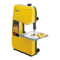
6. Machine set-up
W
arning!
To avoid injury from unexpected starting or electrical
shock, do not plug the power cord into a power
source receptacle during unpacking and assembly.
Never connect the plug to the power source recepta-
cle until the assembly and adjustment steps are com-
pleted, and you have read and understood the safety
and operating instructions. Make certain the switch is
in the off position before connecting the machine to
the power source receptacle.
1Unpack the MICRO Band Saw and check for com-
pleteness.
Note:
For safety reasons the machine should be fastened
with the 3 wood screws (included) to a strong work
bench (see fig. 2). Make sure the MICRO Band Saw is
firmly secured to the bench before use and keep the
floor around the machine clean and free of scrap
material, oil and grease.
6.1. Attaching the work table to the saw
1. Unscrew the brass screw 1 from the sawing gap
(fig. 3) in the working table.
2.Slide the working table 3 (fig. 4) into the respective
recess and fasten it with the knob 2 and the
sleeve1. Set the mark to ”0”.
3.Screw the brass screw 1 (fig. 3) back in.
6.2. Checking and vertical adjusting of the upper
blade guide assembly
W
arning:
Disconnect the machine from the power source!
Properly adjust the blade guides before use!
6.2.1. Vertical adjusting of the upper blade guide
For excellent working results please set the upper
blade guide assembly as close as possible to the top
surface of the work piece.
1. Loosen the knob 1 (fig. 9a) and move the guide
assembly 2 into the desired position.
2.Tighten the knob 1.
6.2.2. Checking and adjusting the blade width
W
arning:
Disconnect the machine from the power source!
Properly adjust the blade guides before use!
Adjust the upper saw blade guide 1 (fig.5) to the width
of the respective saw blade. The edge A must thereby
be in line with line ”5” on the scale (e.g. saw blade
1065 _ ”5” _ 0.4). The band must now touch the rear
roller.
1. Slightly loosen the socket head cap screws with an
Allen key 3 (fig. 5).
2.Slide the adjusting piece (2) until it matches line
”5” on the scale.
3.Tighten the socket head cap screw (3, included),
but not too tight!
4. The saw blade thickness can be corrected by
means of the set-screw 4.
6.2.3. Using a vacuum cleaner
Note:
When cutting wood or plastic materials the machine
should be connected to a dust extractor (vacuum
cleaner) to avoid accumulation of saw chips inside the
machine.
1. Connect the vacuum cleaner to the rubber socket
1 (fig. 6).
Please first make sure that the plate 1 (see fig. 7) is
inserted. This is necessary when often sawing wood or
similar materials.
When often cutting aluminum, metal, glass, tiles etc.
remove this plate to avoid accumulation of chips
inside the machine.
2.Unscrew four socket head cap screws 2 from the
housing 1 (fig. 1) and take the cover off.
3.Slide the plate 1 (fig. 7) in and connect the vacuum
cleaner to the socket 1 (fig. 6).
4. Install the housing cover.
- 8-