-12-
However
,this causes the top slide to shift by 0.025 mm to the left
and the same distance to the right.
The
chip in the thread is thereforealways only removed from one side.
Once the full thread depth has been reached, afinal full cut is
made
by advancing slightly.
Cutting left threads
To cut left threads, the intermediate gear 1 (Fig. 21) must be instal-
led between "Z
1
-Z
2
"and the leadscrew gear "L1".
In doing so, the turning direction of the leadscrew is reversed. The
support
runs from right to left when the chuck is turning clockwise.
Installation and operation areasdescribed above.
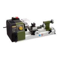
Accessories for Lathe PD 250/E
Note:
The
described accessories arenot included in the standardequipment.
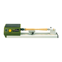
Installing the centrelathe (No. 24014)
When using acentrefixed to the tailstock, regular lubrication of
the centreand centreboreisnecessary to prevent the temper
from loosening.
Note:
Longer work pieces areclamped between the brad points of the
main spindle and tailstock.
The work piece must have acentreboreonboth faces.
An exact cylindrical work piece is only achieved if the points align
in the horizontal position.
1. Remove three fastening screws from the three-jaw chuck and
remove chuck.
2. Thoroughly clean the fit for the driving disc and centreand its fit
in the main spindle.
3. Insert the centre 4 (Fig. 22) in the fit (1) of the main spindle.
4. Fit the driving disc (2) and fasten with three screws (3).
5. Push the lathe carrier 1 (Fig. 23) onto the work piece (driving
pin outwards) and tighten the fastening screw (2).
6. On the left side, insert driving pin in one of the three long holes
on the driving disc and the centreinthe centrebore.
7. On the right side, attach the work piece using the tailstock and
fixed or rotating centre.
8. To remove the centre, guide asuitable aluminium or brass rod
through the main spindle from left to right.
9. Hold the centreand release by lightly tapping the rod.
Four-jaw chuck (No. 24036)
In the normal clamping jaw position, only work pieces with an
edge of up to max. 30 mm long can be clamped. The maximum
length is 80 mm in the reverse position.
Larger work pieces arenot securely held. Danger of accident.
Collet chuck unit and collet chucks
Remove mains plug.
Note:
Round, oval, squareand irregularly shaped work pieces can be
clamped as it is possible to adjust the jaws individually.
Centric
or eccentric clamping is possible.
Unlike the threejaw chuck, centring of the work piece must be per-
formed
manually.
1. Detach the three-jaw chuck and attach the four-jaw chuck.
2. Open the four jaws, clean the contact faces and clamp the
work
piece lightly according to visual estimation.
3. Move the support and turning tool onto the plane surface of the
work piece.
4. Turn the chuck by hand to establish symmetrical deviations.
6.
Adjust by opening one of the jaws and reset the opposite jaw
accordingly.
7. Tighten all four jaws evenly,alternating crosswise.
Collet set with ER 20 collets (No. 24038)
Important
Always
use the correct collet chuck to suit the work piece.
Chucks with an oversized diameter aredestroyed.
Important
Never tighten the union nut when thereisnowork piece inserted.
The collet chuck unit is especially suitable for processing round
parts with great precision. The truth of running is considerably
greater than when working with ajaw chuck.
1. Remove three fastening screws from the threejaw chuck and
remove chuck.
2. Thoroughly clean the fit for the collet chuck mount 2 (Fig. 24)
and the fit in the main spindle (1).
3. Attach the collet chuck mount (2) using four fastening screws (3).
4. Insert the collet chuck (6) and loosely screw in the union nut (5).
5. Insert the appropriate work piece in the collet chuck and tighten
the union nut (5) using the tool pins (4).
6. Remove the pins 4(Fig. 24) for tightening the union nut (5)
immediately after tightening.
Fastening the drill chuck (No. 24020)
The jaws (2) must only touch the work piece and must not jam.
Otherwise thereisarisk of the work piece surface becoming
scratched and the motor becoming overloaded.
1. Remove the rotating centrefromthe sleeve. Thoroughly clean
the grease and dirt from the shank taper and chuck bore.
2. Insert the journal in the sleeve and firmly push onto the drill
chuck.
Note:
Releasing the drill chuck is performed in the same way as the
rotating centre.
Fixed steady (No. 24010)
The steady is particularly suitable for hollowing out long work
pieces with diameters up to 40 mm.
1. Release the fastening screw 4 (Fig. 25) and position retaining
plate (3) crosswise.
2. Place the steady on the bed guide and set to the required
position.
3. Swivel the retaining plate (3) parallel to the steady base and
tighten fastening screw (4).