Installation position
Outdoor usage:
When using the actuators in environments with high
temperature fluctuations or high humidity, we recommend
using a heating resistor.
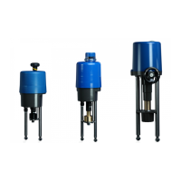
5. Function
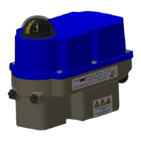
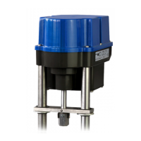
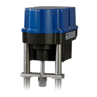
The PSF actuators are designed as electric valve actuators with failsafe function. The actuator is mounted onto the
valve via pillars. Depending on the type of valve used, mounting pillars or a special valve mounting bracket is
required.
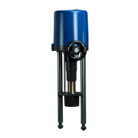
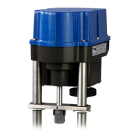
Based on a brushless DC motor (BLDC) the generated torque is transmitted via a multi-stage spur gear onto a spindle
nut. The spindle nut transmits the input torque into an axial thrust force via a spindle. The linear stroke is
transmitted to the valve spindle by a coupling piece.
The stroke is measured and controlled by a linear 12 Bit Hall sensor.
In case of mains power loss, the stroke movement is in OPEN or CLOSE direction by spring force.
Electrical wiring is done to a terminal block under the actuator cover.
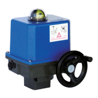
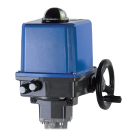
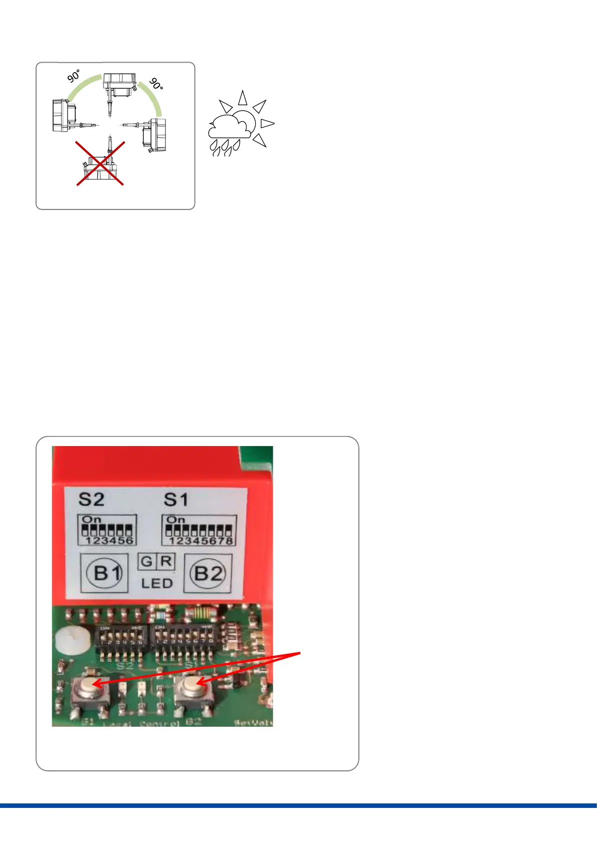
6. Manual operation
Two push buttons are installed to
drive the actuator in case of
installation work such as mounting
onto a valve, or setting the limit
switches positions (see 10.7).
Push
buttons
 Loading...