13
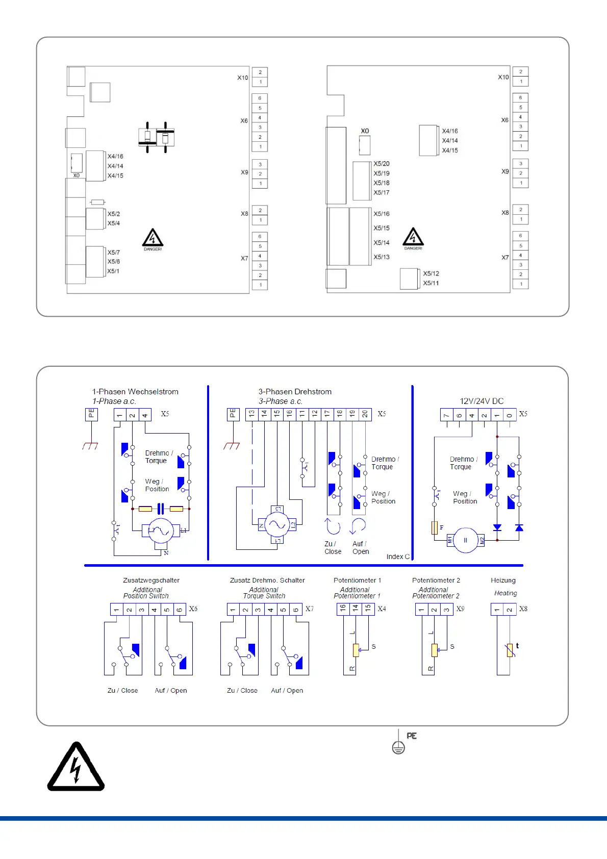
Figure 16: Wiring terminals
X0 = Potentiometer, internal wiring
X10 = Normally OPEN contact option
Figure 17: Wiring diagram
PE earth connection has to be connected to gear casing at !
Ensure that all connecting cables are stripped to the correct length so that they are protected
against electric shock.
Wiring terminals 1~
Wiring terminals 3~
 Loading...