10
Ensure that the mains supply is secured against accidental switching-on!
Run the actuator electrically to the closed position until the valve is closed and the actuator is switched off by the
torque switch.
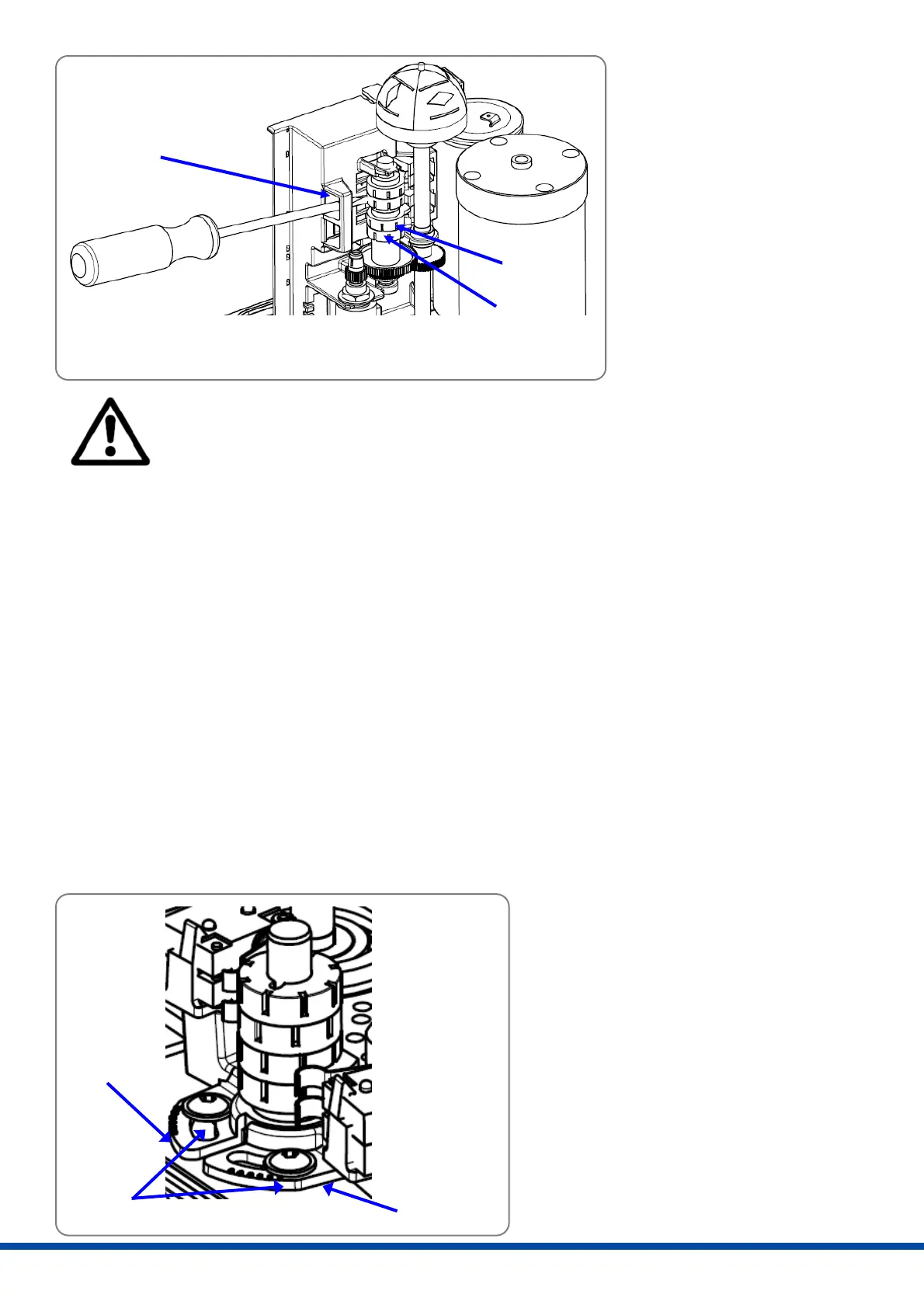
Turn the cam of the CLOSE position switch (Figure 11, item 1 and Figure 12, item 2) with an isolated screw driver
(4 mm blade width) anti-clockwise until the micro switch is heard to click.
Run the actuator electrically to the open position until the valve is fully open and the actuator is switched off by
the torque switch.
Turn the cam of the OPEN position switch (Figure 11, item 2 and Figure 12, item 1) with an isolated screw driver
(4 mm blade width) clockwise until the micro switch is heard to click.
Drive the actuator away from either end position to release the stop screws.
Turn both stop screws counter-clockwise by one turn.
Replace protection caps (Figure 7, item 3) onto the stop screw holes after setting the position switches.
10. Setting the torque limit
There is one torque switch installed for each direction that cuts off the motor current when operated (single phase
motors).
The quarter-turn actuator is set and checked by the manufacturer in order to limit the actuator to the nominal
torque in both directions. The reduction of the maximum output torque is possible by setting the switch brackets, to
suit the specific requirements of the valve.
Loosen the torque setting screws (Fehler!
Verweisquelle konnte nicht gefunden
werden., item 3) and turn the switch
brackets to the required position.
Fix this positions by tightening the screws.
Item 1: Switch bracket „CLOSE“
Item 2: Switch bracket „OPEN“
Item 3: Fixing screws
1
3
2
3
2
1
Figure 12: Setting the switching cams for position switches PSQ2003/2803
Item 1:
Switching cam OPEN position
Item 2:
Switching cam CLOSE position
Item 3:
Bridge for screw driver support
 Loading...