7
7. Valve mounting
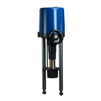
7.1. Valve mounting PSQ103-1503
The PSQx03 actuators are provided with flanges according to ISO 5211 for valve mounting. Connection to the valve
shaft is made with an exchangeable drive bush.
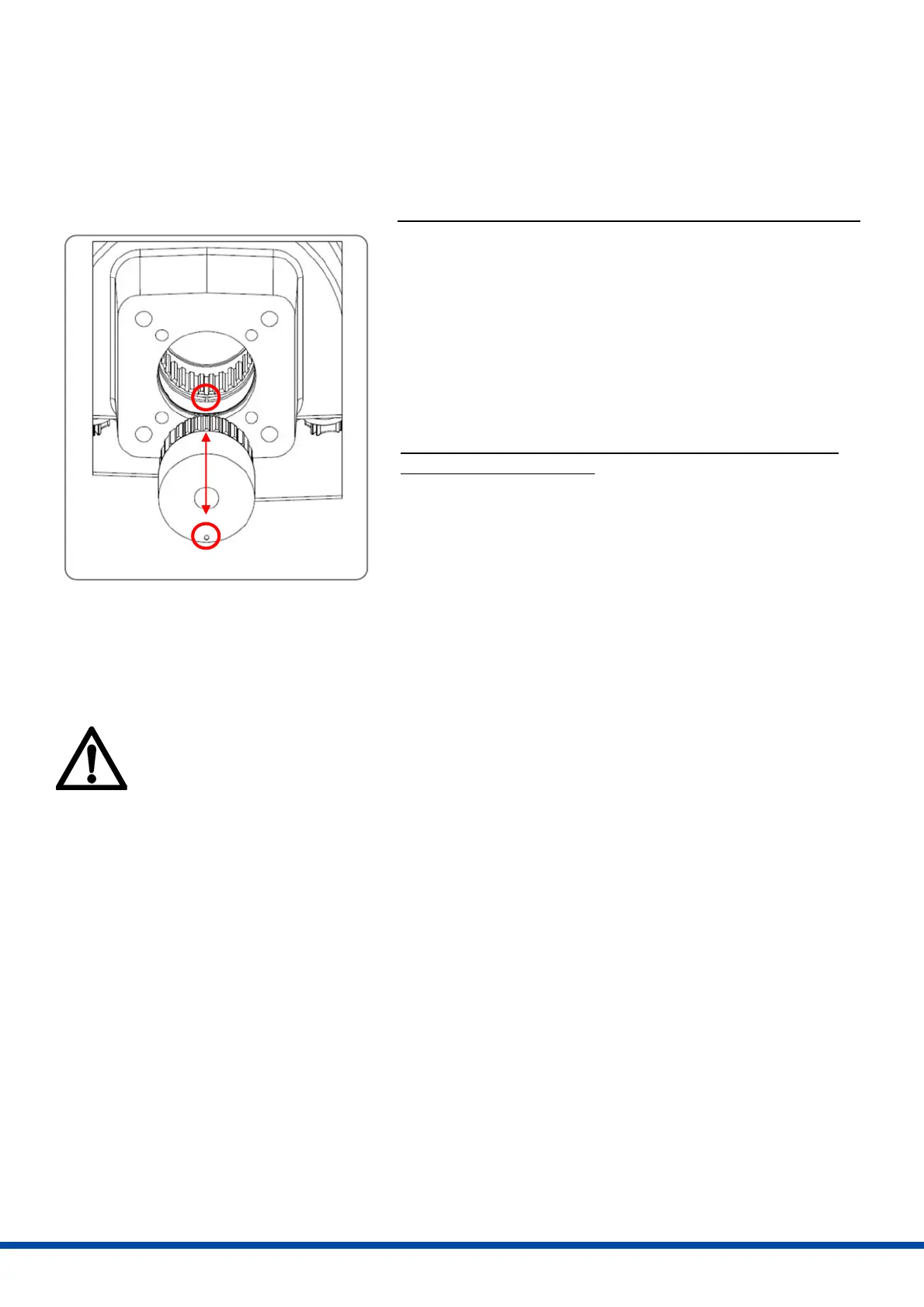
Starting position: drive bush is already pre-installed in the actuator
Ensure the correct position of the actuator by position indicator
and adapt it to the position of the valve by handwheel. Ideally,
the end position of the valve should be open or closed. Drive the
actuator in the same end position by handwheel.
If the positions of valve and actuator are adapted, put the
actuator with the drive bush on the valve.
Adapt the accurate mounting position by handwheel to insert
the screws in the mounting flange. Tighten the screws in a
diagonal sequence.
Starting position: drive bush is delivered separately and not yet
pre-installed in the actuator
Put the drive bush on the valve shaft first.
Follow the instructions of the pre-installed drive bush above.
However, please note: The drive bush is not installed in the
actuator for mounting on the valve shaft. Instead, the drive bush
is already mounted on the valve shaft as a unit. Put the actuator
on this unit.
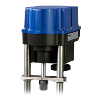
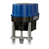
7.2 Valve mounting PSQ2003/2803
The PSQx03 actuators are provided with flange F16 according to ISO 5211 for valve mounting. Connection to the
valve shaft is made with a 55 mm double square. Delivery of the actuator includes two components: the gearbox and
the actuator itself. They are mounted on the valve one after the other.
For valve mounting please ensure that the cover of the actuator is always closed in order to avoid
that components inside the actuator are damaged.
Ensure the correct position of the gearbox by position indicator and adapt it to the valve position using a 22
mm spanner to turn the shaft of the gearbox. In the best case, the position of the valve should be open or
closed during mounting. If possible, drive the valve to one of the end positions manually. Drive the gearbox
in the same end position using the spanner.
If the gearbox and actuator are in the same position, mount the gearbox on the valve (if necessary, mount
the adaptation of the valve shaft on the 55 mm double square first).
Adapt the accurate mounting position with the spanner in order to insert the screws in the mounting flange.
Tighten the screws in a diagonal sequence.
Put either (A) the actuator with the drive bush on the gearbox or (B) at first the drive bush and then the
actuator on the gearbox (see figure 6 for reference).
Adapt the accurate mounting position by handwheel to insert the screws in the mounting flange. Tighten
the screws in a diagonal sequence.
Fi
ure
: Mechanical inter
ace
 Loading...