32
ELECTRIC COMPONENTS INSTALLATION
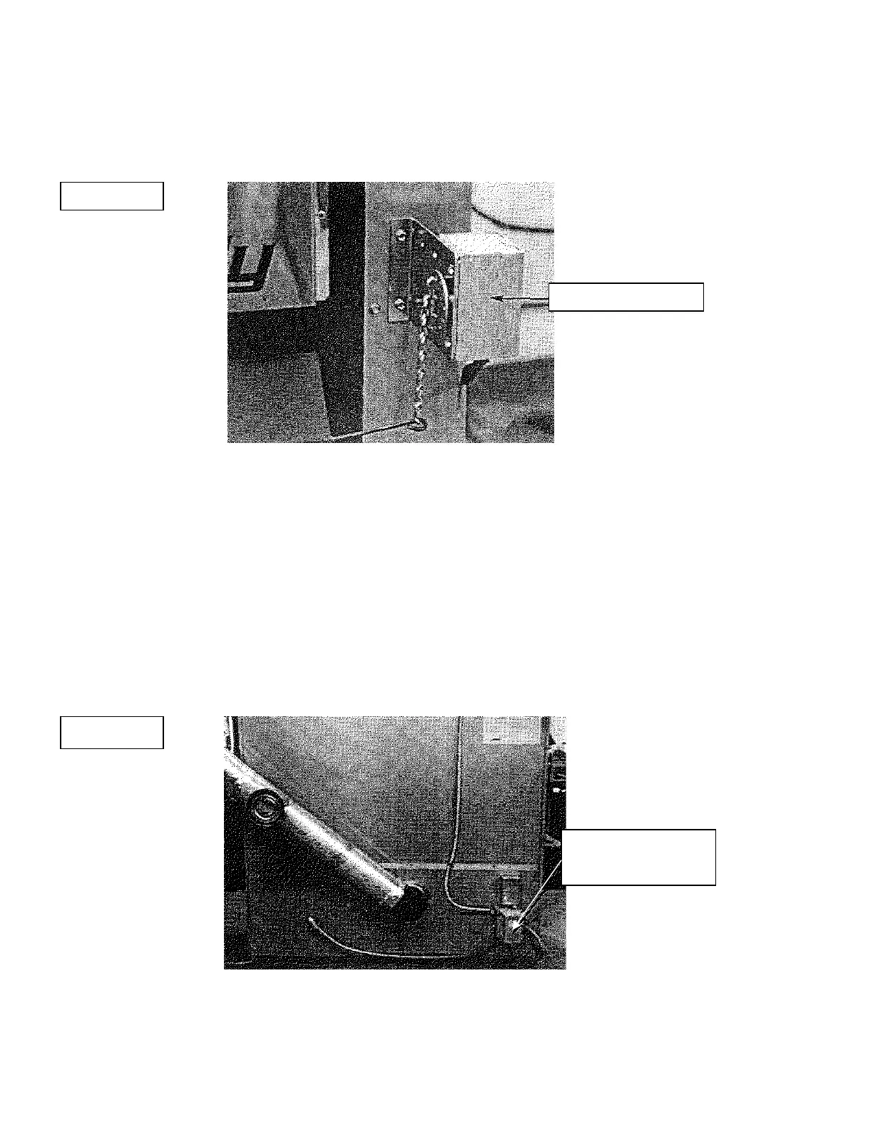
All the wires joining the electric components must have the proper length. Run the wires connecting the
servo-motor to the relay-transformer away from surfaces that may get hot (see figure #1).
FAN LIMIT INSTALLATION ON PSG UH-2000-3000 AND 4000 MODELS
The wood fan limit control must be installed with the mounting bracket, in the warm air plenum on the left
hand side of the appliance; two holes are pre-drilled on the edge to match the holes on the mounting
bracket (see fig. #3). On the PSG3000, there are four pre-drilled holes, use the ones located further back.
The fan limit control for the oil unit (affixed to the junction box and relay-transformer, see figure #2) must
be installed on the lower left hand side removable panel, near the oil flue outlet; a 1" diameter hole is pre-
punched to allow the insertion of the fan limit’s probe).
FIGURE #1
FIGURE #2
SERVO-MOTO
RELAY
TRANSFORMER