Go to Contents Precise Time and Frequency, Inc., 50L Audubon Road, Wakefield, MA 01880, USA ptf 3207A rev G
Tel: +1-781-245-9090 e-mail: info@ptfinc.com www.ptfinc.com pg. 18
*****************************************************************************
Making Additional Connections
Make the following connections to the standard input/output connectors on the ptf 3207A rear panel:
• The ANTENNA connector to a GNS antenna cable.
• The ENET Ethernet port (RJ-45) to an Ethernet network using Cat 5 cable. This
connection is needed to manage the ptf 3207A remotely, or to use the optional NTP function.
• The SERIAL I/O connector to a PC using an RS-232 null modem cable.
• J1 thru J12 as needed.
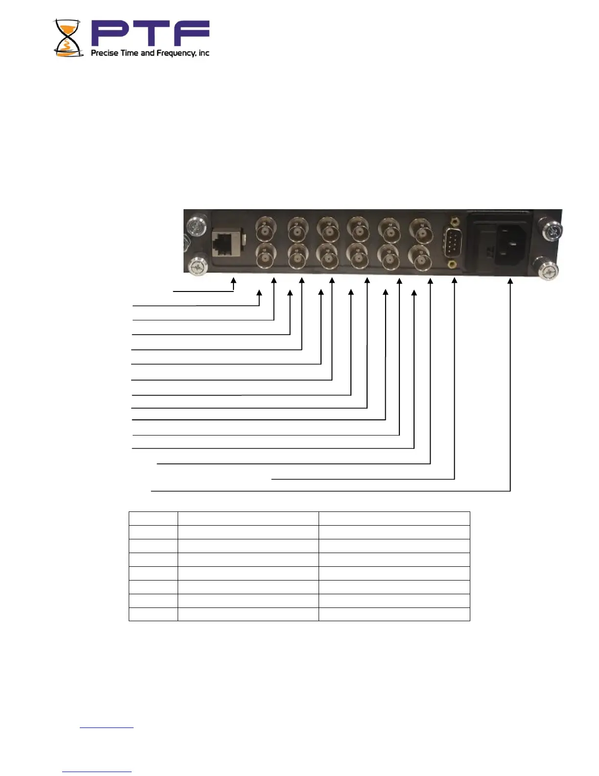
Rear View of single
Module
Connections
J1 (Ethernet, RJ45)
J2 (lower)
J3 (upper)
J4(lower)
J5(upper)
J6(lower)
J7(upper)
J8(lower)
J9(upper)
J10(lower)
J11(upper)
J12(lower)
J13(upper)
J14(RS232 control/monitor/alarms relay)
J15(AC Mains)
NOTE: There are many different configurations that necessarily require different input/output
connections. In some cases many of the connections will be blank. For each specific instrument
connections are detailed on a label above the input/output connectors. Where this label differs from
the connections outlined above, the label always takes precedence.