26
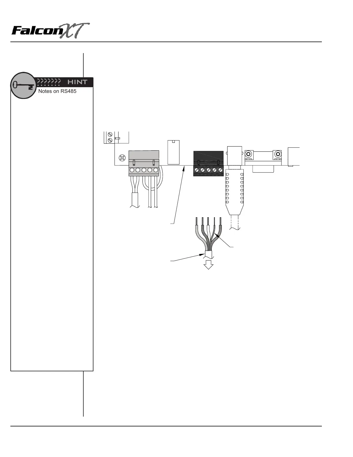
4. Repeat this process with the rest of the wires as follows:
• Slot 1: Red DC +
• Slot 2: Black DC –
• Slot 3: White Data +
• Slot 4: Shield Wire *
• Slot 5: Green Data –
* The shield wire is bare inside the cable. It should be insulated using electrical tape or
heat shrink insulation.
POWER &
BATTERY
ACCESS
INTERFACE
(AI) DEVICES
USB
RS232C
12VDC (RED)
GND (BLK)
DATA+ (WHT)
SHIELD
DATA-(GRN)
CONTROLLER
INSULATED SHIELD WIRE
4-CONDUCTOR, 18GA,
SHIELDED CABLE
TO ALL
DEVICES
Notes on RS485
Remember, splices should be
kept to a minimum. RS485 splices
should be made using 3M U-Type
connectors and crimpers only. It
is better to pull a single new cable
instead of splicing. See the Wire
Splicing section in Chapter 1 for
more information.
During retrots and change-outs,
we do not recommend using
existing wire that has already
been pulled on a site. It is
impossible to know the condition
of this wire and the site may
experience costly troubleshooting
and service calls due to problems
with older wiring or wire types
that are not recommended by PTI
Security Systems.
We do not recommend that
RS485 be run more than 4000’ in
a single run.
Engineering Specications for
RS485 recommend that the wire
be run in series from the controller
to the rst AI device, then from the
rst AI device to the second, from
the second to the third, and so on.
Due to site layout considerations,
it may not be possible to go from
one device to another in order.
At times a second line must
be run from the controller to a
different section of the property.
However, it is important to avoid
star patterns in the wiring, where
an individual cable is run to each
AI device as this makes future
service and troubleshooting
almost impossible.