ChapTEr 2: INSTallaTION
29
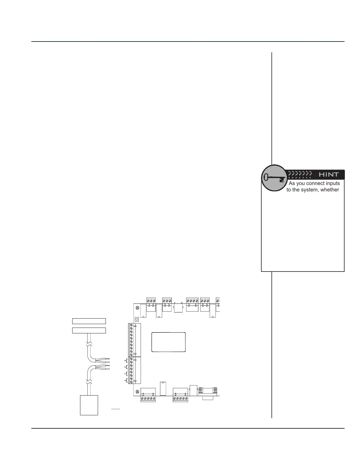
Door Input Connections
There are eight door input relays on the controller circuit board. Door
Inputs 1 – 4 are on the lower left side of the board and Inputs 5 – 8
are on the lower right. These door inputs can be used for door alarm
switches, request-to-exit switches, motion sensors, photobeams,
pressure pads, and many other types of dry contact switches.
1. To connect door Input 1, run the two wires from the switch
into the controller housing. Strip ¼ inch of insulation from the
end of each of the individual conductor wires. Connect one
of the wires to the rst terminal slot marked Input 1. Connect
the second wire to the second terminal slot marked Input 1,
immediately below the rst terminal slot. Use a small, athead
precision screwdriver to tighten down the terminal screw to
rmly hold the wire in place. Verify that the wire is rmly held by
tugging slightly on it. Verify that the terminal screw is tightened
down on the bare copper wire and not the insulation, but
make sure that there is no copper wire showing outside of the
terminal block.
2. Repeat the process in Step 1 above for each of the eight
door inputs. Be sure that each set of wires is clearly marked
so that it is easy to tell which door switch or other device it is
connected to. This will be very important when programming
the control software.
3. Once all of the door inputs have been connected, they must be
programmed in the control software. Refer to the software Help
Files for more information.
As you connect inputs
to the system, whether
on the controller circuit board, on
door alarm multiplexers, or on the
keypads, keep a written record of
the input number cross-referenced
with the door unit number or
location where the input is
connected. This will be used when
setting up the control software.
After the software is set up, this
written record should be kept with
the manuals for future reference.
RED LED
WIEGAND 1
WIEGAND 2
DATA 0
INPUT 4
INPUT 2
INPUT 3
INPUT 1
BEEPER
TMPR/CP
HOLD
DOOR INPUTS
DOOR INPUTS
INPUT 5
INPUT 7
INPUT 6
+12V
+5V
GND/SHLD
INPUT 8
NC
NC
GND/SHLD
GRN LED
DATA 1
DATA 0
+5V
+12V
NO
COM
COM
NO
NC
+12V
RX
GND
NO
TX
COM
RED LED
DATA 1
GRN LED
HOLD
TMPR/CP
BEEPER
COM
NO
NC
12VDC POWER
SUPPLY
(DEDICATED TO
DOOR STRIKE)
12VDC DOOR
STRIKE
RED
BLACK
DC
+-
NO
COM
120VAC
PUSH
TO
EXIT
CONTACT
MAGNET
REFER TO GATE OPERATOR
MANUFACTURER INSTRUCTIONS
FOR PROPER WIRING TO RELAY.
GATE
OPERATOR
12VDC POWER
SUPPLY
(DEDICATED TO
SIREN)
DC
+-
120VAC
SIREN
REFER TO
MANUFACTURER'S
INSTRUCTIONS FOR
WIRING WIEGAND
DEVICES.
RELAY 1
RELAY 2RELAY 3
RELAY 4
-
+
NOTE: RUN CABLES THROUGH HOUSING
KNOCKOUT/CONDUIT BEFORE WIRING TO BOARD.
ZNR Surge Absorber
(MOV)
(TO RELAY 4)
(FROM SIREN)