11984 Rev01 Page 7 of 15
3.1 Installation
Supervisor Power and Signal Connection from Supervisor to Furnace
I - Caution: Prior to installing or removing SENTRY 1510 system
cabling, make sure the Supervisor power switch is in the OFF
state. Turn the Supervisor power switch ON once all cabling has
been installed.
Power for the Supervisor can come from the process tool controlleror from a stand-
alone power supply. The set point can come from an externally generated signal
(i.e. from the process tool controller) or it can be manually entered into the
Supervisor. Signal connection can be made through an RS422/RS485 interface or
a 0-5 V analog interface. The interface options are given in Appendix A.
Determine which interface is applicable, then go to the appropriate section for in-
structions.
Stand Alone Operation
In this configuration, the SENTRY system derives its power from a stand-alone
power supply. The cable set is based on the voltage available, and is designed for
standard available power connections. (section 7, page 1. gives part numbers for
cables of different voltages.)
0-5 Volt Analog Interface Powered from the Process Tool Controller
In this configuration, the SENTRY system derives its power from the standard DC
power distribution system in the furnace. The Host to Supervisor cable (see
section 7, page 1.) is used to integrate the Supervisor with the furnace voltage
supplies and the analog set point control interface. SENTRY system uses +15 to
+24 V and -15 to -24 V for power input (see section 7, page 4. for allowable
voltage and current ranges). The electrical requirements for the SENTRY 1510
are similar to most gas mass flow controllers, which allows a typical mass flow
controller port to control the SENTRY. The process tool controller is able to control
the exhaust set point by the 0-5 V analog set point signal that is transmitted to the
Supervisor. The Supervisor uses an analog to digital converter to convert the set
point signal to a digital number. Based on a change in the set point command
signal the Supervisor commands the SENTRY 1510 to the new exhaust set point.
On a continuous basis, the actual process static pressure level is transmitted by
the Supervisor back to the furnace.
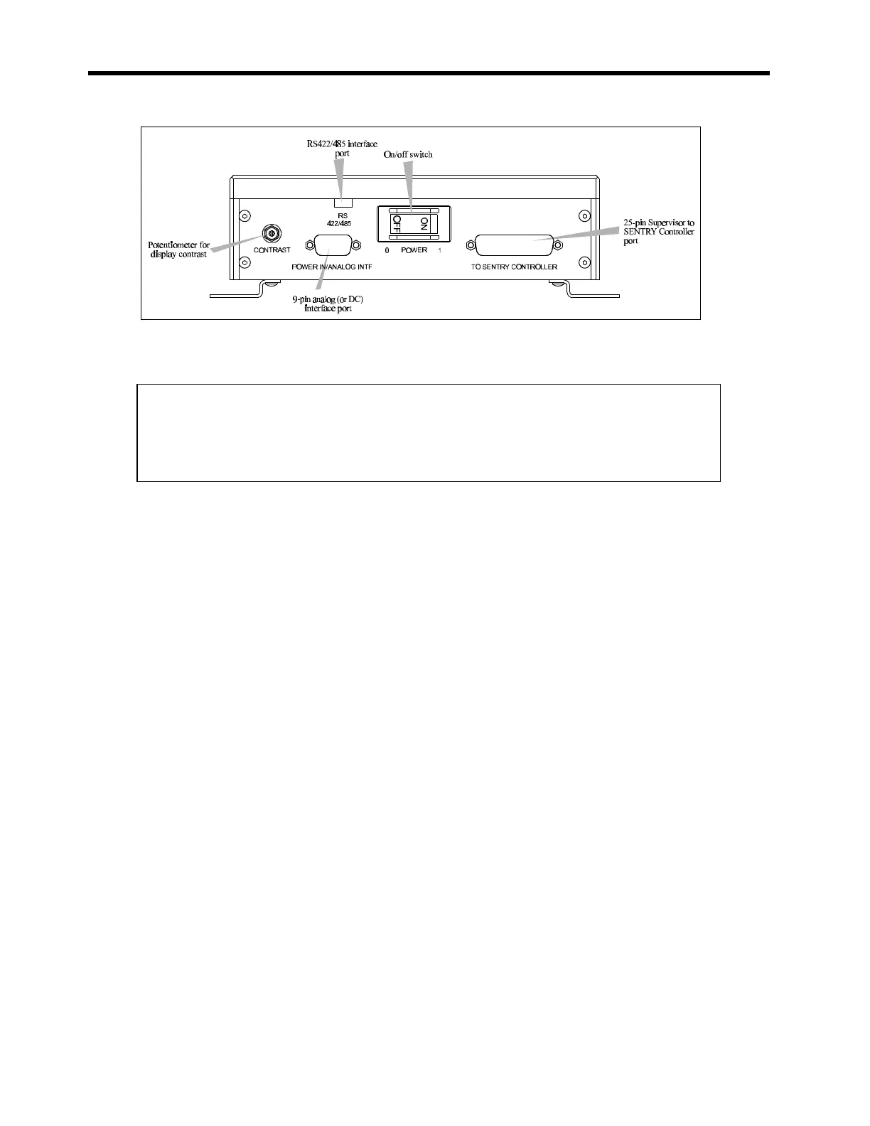
Figure 3-5 : Cable connections are clearly marked on the SENTRY
Supervisor.