PAGE 3
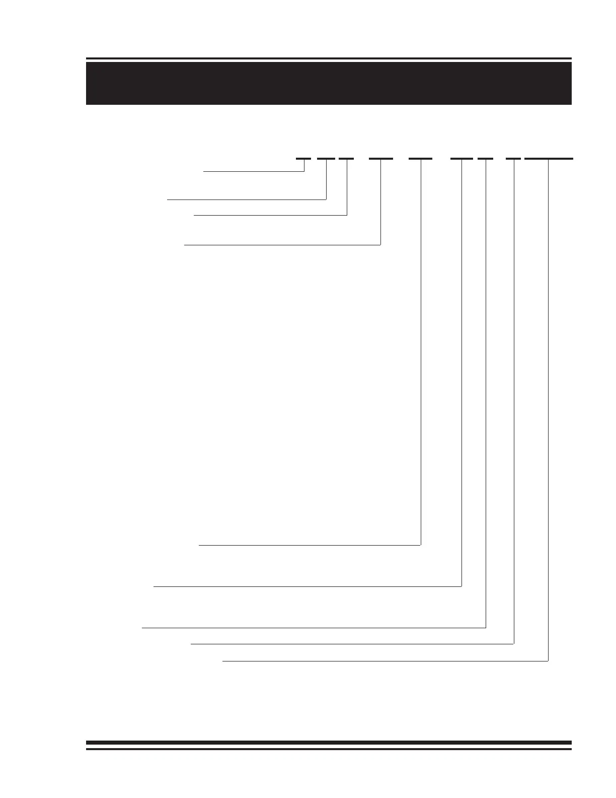
X - XX - XX - XX X - X XXXX
253 REV.980701
M
50
EXPLANATION OF MODEL CODING
BASIC UNIT SERIES
M = Equal speed in both directions
SIZE OF UNIT
REDUCTION RATIO
Only used for non standard reduction ratios
TYPE OF BRAKE
-0 Winch without brake
-3 Automatic brake, clockwise drum rotation, internal circulation flow
-4 Automatic brake, external brake release, clockwise drum rotation,
internal circulation flow
-5 Automatic brake, external brake release, counterclockwise drum
rotation, internal circulation flow
-6 Automatic brake, counterclockwise drum rotation, internal
circulation flow
-7 Automatic brake, clockwise drum rotation, external circulation flow
-8 Automatic brake, external brake release, clockwise drum rotation,
external circulation flow
-9 Automatic brake, external brake release, counterclockwise drum
rotation, external circulation flow
-10 Automatic brake, counterclockwise drum rotation, external
circulation flow
-11 Brake effective in both directions, external circulation flow
-17 Brake effective in both directions, external circulation flow,
external drain, external brake release
HYDRAULIC MOTOR
-86 Hydraulic motor, 3 inch gear section (12.3 cubic inch displacement)
(Other gear sections for this motor are optional)
DRUM SIZE
-1 14 inch drum diameter X 23.75 inch flange diameter X 14 inch length -
STANDARD
(For other drum sizes refer to APPENDIX A)
OPTIONS
DESIGN REVISION
SPECIFICATION NUMBER
Describes features not identified by preceding codes
NOTE: Clockwise and counterclockwise drum rotation is the direction of rotation for pulling or hoisting,
established by looking at the hydraulic motor.