PAGE 17
SERVICE INSTRUCTIONS CONTINUED
f
249 REV.970901
engaging planet gears with internal gear. Fasten with retaining ring, item 401.
9) Insert final sungear, item 340, into cable drum and engage three planet gears, item 320.
10) Lower brake housing assembly onto cable drum, while engaging spline of final sungear with primary planet
hub, item 400. Line up mounting holes of bearing flange, item 530, with those in cable drum.
11) Rotate brake housing to line up access holes and fasten bearing flange using six capscrews, item 537, and
lockwashers, item 541.
12) Install new, well-greased O-ring, item 735, into access plug, item 734. Install access plug into access hole
inside brake housing.
13) Attach base halves, items 550 and 552, using 28 capscrews, item 551, and lockwashers, item 553.
REASSEMBLY OF BRAKE HOUSING ASSEMBLY:
Reassemble brake housing assembly as follows:
1) Install sprag clutch, item 723, into bore of brake hub, item 720. Position sprag clutch aligners, items 722 and
724, on either side of brake hub. Carefully slide motor drive shaft, item 730, into brake hub assembly and
secure with circlip, item 727. Verify that circlips, items 719 and 731, are installed on motor drive shaft.
2) Carefully slide motor drive shaft, item 730, with brake hub assembly, into connecting shaft until it engages
spline of primary sungear, item 440.
IMPORTANT: For proper brake function, verify that sprag clutch is installed correctly. When viewed from
the motor end, the motor drive shaft of a clockwise hoisting winch must turn freely clockwise
and lock in the counterclockwise direction.
3) Install brake spacer, item 712, into brake housing.
4) Starting and finishing with a divider plate, alternately install six divider plates, item 713, and five friction
plates, item 715.
5) Liberally grease O-ring, item 751, and O-ring, item 753, and install on brake piston, item 750.
6) Slide brake piston into brake housing with holes for brake springs facing out of brake housing assembly.
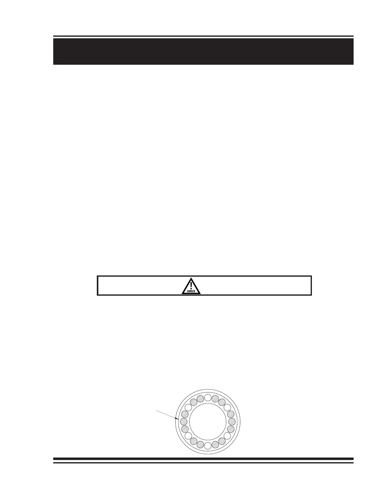
7) Install 14 brake springs, item 752, in brake piston using hole pattern shown:
SI1007 - M25
INCORRECT ASSEMBLY OF THE FRICTION PLATE AND DIVIDER PLATE
STACK WILL REDUCE BRAKING CAPACITY AND ALLOW THE LOAD
TO DROP, CAUSING PROPERTY DAMAGE, SEVERE INJURY OR
DEATH. REASSEMBLE PER INSTRUCTIONS.
LOCATION OF
BRAKE SPRINGS
(FOURTEEN SPRINGS,
TWENTY HOLES)