PAGE 18
SERVICE INSTRUCTIONS CONTINUED
253 REV.980701
8) Liberally grease three new O-rings, item 801, and install into recesses on motor adaptor, item 800. Install
new, well-greased O-ring, item 707, on flange of motor adaptor.
9) Slide hydraulic motor assembly onto splined end of motor drive shaft, item 730, and line up pressure transfer
holes of brake housing and motor adaptor. Install 12 capscrews, item 537, and lockwashers, item 541.
Tighten one turn at a time to evenly compress springs.
REASSEMBLY OF HYDRAULIC MOTOR:
If the hydraulic motor was disassembled, the following procedure should be followed for reassembly:
1) Clean all parts thoroughly before reassembly and apply grease liberally to all seals. Use only new seals (seal
kit Part No. 23117) for hydraulic motor.
2) Install two new teflon seals, item 887, on each thrust plate, item 885. Press one thrust plate, together with
two teflon seals, onto bearings, item 875, installed in motor adaptor, item 800.
3) Install new, well-greased gasket seal, item 869, on each side of gear housing, item 861. Slide gear housing
together with gasket seals, onto motor adaptor, lined up on two dowel pins. Tap on tight using soft headed
hammer.
4) Install gear set, item 881, into gear housing. (The longer gear with the internal spline goes into the top
position.)
5) Press remaining thrust plate, complete with two new teflon seals, onto bearings installed in port end cover.
6) Install port end cover, item 870, together with two bearings, item 875, and new ring seal, item 877, onto gear
housing, lined up on two dowel pins, item 865. Tap on tight using soft headed hammer. Install and lightly
torque eight hex capscrews, item 951, and lockwashers, item 953, to approximately 50 ft-lb (70 Nm).
SI1007 - M50
4) Starting and finishing with divider plate, alternately install six divider plates, item 713, and five friction plates,
item 715.
5) Liberally grease O-ring, item 751, and O-ring, item 753, and install on brake piston, item 750.
6) Slide brake piston into brake housing with holes for brake springs facing out of brake housing assembly.
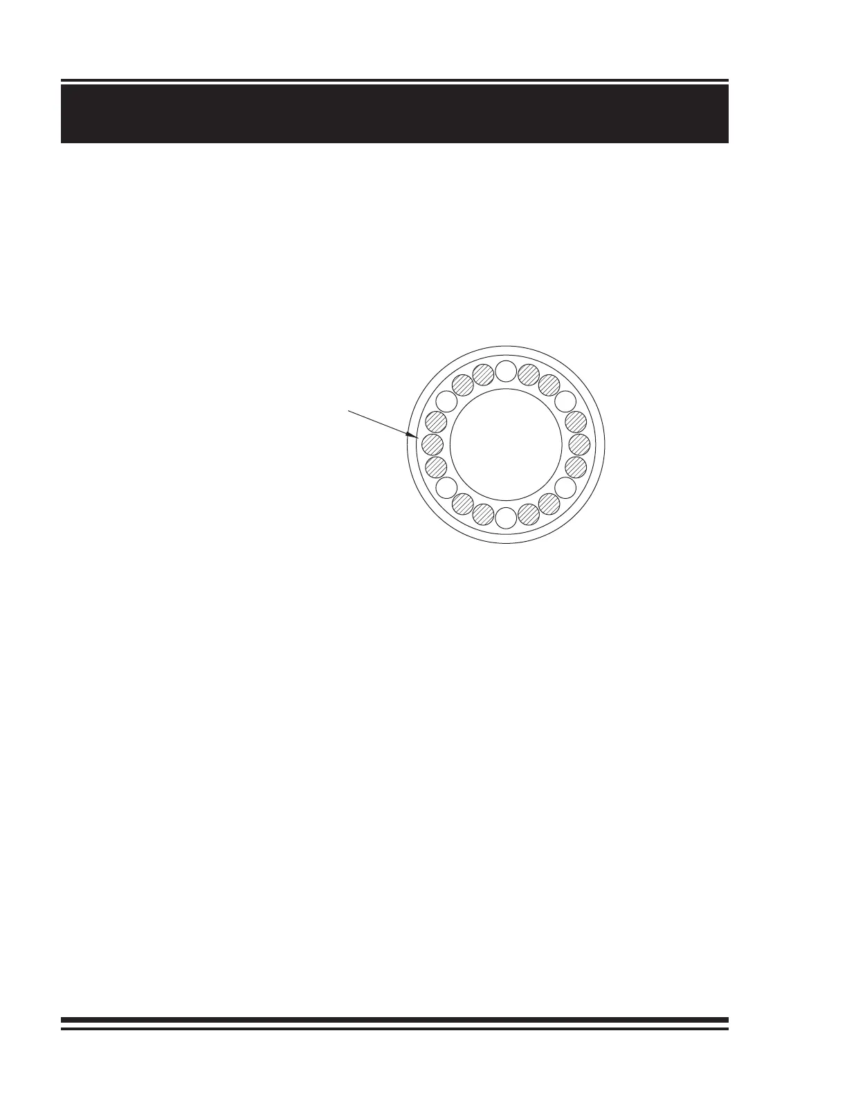
7) Install 14 brake springs, item 752, in brake piston using hole pattern shown:
Location of brake springs
(14 springs, 20 holes)