PAGE 18
316 REV.980601
SERVICE INSTRUCTIONS CONTINUED
SI-1029
REPLACEMENT OF HYDRAULIC MOTOR ASSEMBLY:
Replace the hydraulic motor assembly by reversing the removal procedure.
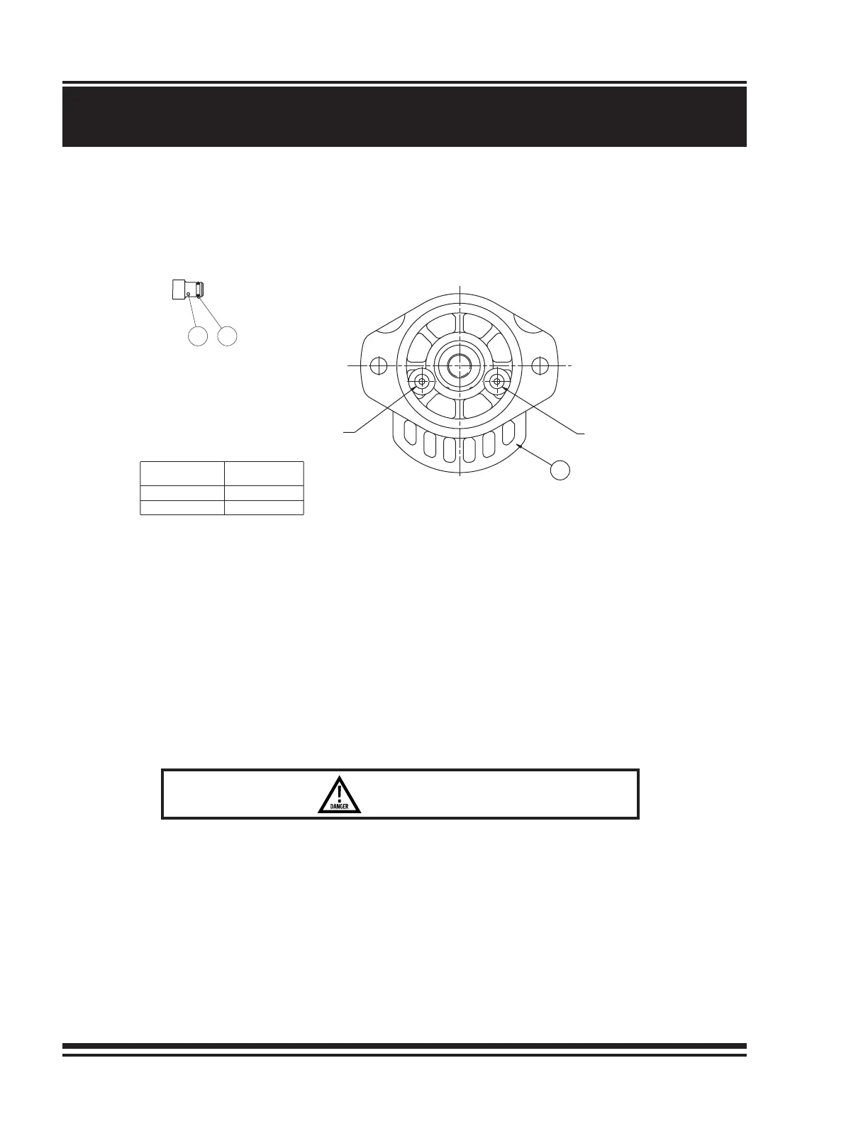
IMPORTANT: Before installing motor, determine brake code of winch. Install motor plug as indicated below.
1) Install three new, well-greased O-rings, item 831; two onto connecting tube, item 830, and one onto motor plug,
item 888. Install connecting tube and motor plug into motor, item 950. Verify that holes are same as parts were
removed from.
2) Install new, well-greased O-ring, item 811, onto motor pilot, item 950.
3) Fasten motor to motor adaptor using two capscrews, item 935, and lockwashers, item 937.
IMPORTANT: Before operating the winch, add lubricating oil up to the level of the end housing oil fill port.
(Refer to INSTALLATION INSTRUCTIONS for location of fill port. Refer to APPENDIX A for
oil volume required.)
To ensure proper reassembly, run the winch in both directions without load.
LIFTING A LOAD WITH A NEWLY SERVICED WINCH WILL ENABLE
AN INSTALLATION OR SERVICE PROBLEM TO GO UNDETECTED AND
ALLOW THE LOAD TO DROP, CAUSING PROPERTY DAMAGE, SEVERE
INJURY OR DEATH. TO ENSURE PROPER REINSTALLATION, REFER
TO PROCEDURES AND TESTS DESCRIBED IN "INSTALLATION" AND
"OPERATING INSTRUCTIONS".
DANGER
950
888 831
-6
A
B
-3
PLUG PORT
BRAKE CODE
NOTE:
INSERT MOTOR PLUG, O-RING END
FIRST, INTO PORT A OR B AS
INDICATED IN CHART BELOW.
MOTOR PLUG
WITH 0-RING
(MAY NOT BE EXACTLY AS ILLUSTRATED)
SHAFT SIDE OF MOTOR
BRAKE RELEASE
PORT ’B’
BRAKE RELEASE
PORT ’A’