10.4 Phase Adjustment
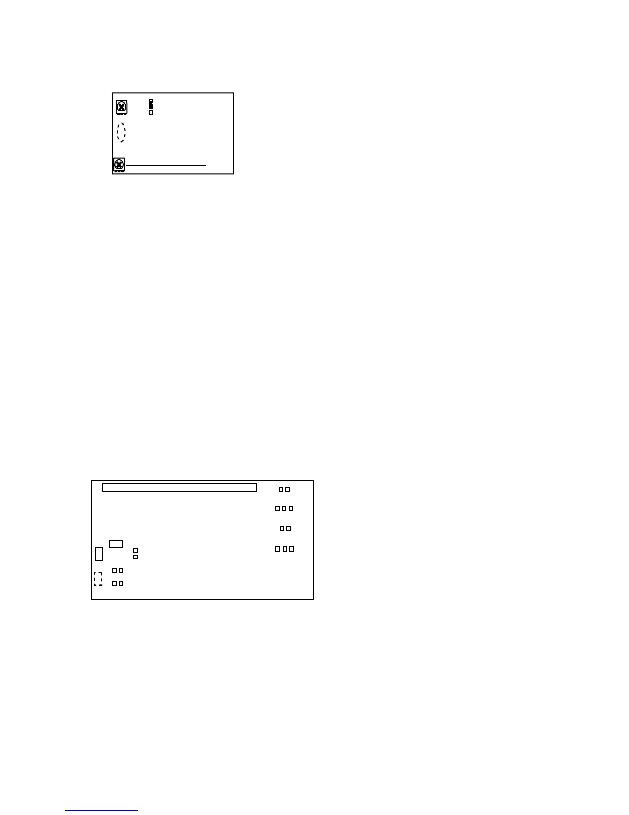
TM-7EX GENLOCK BOARD
Horizontal Lock
Apply HD to Genlock board and probe internal HD.
Both External HD and Internal HD phase should line
up. Observe jitter. It must be less than 20 nsec.
Adjust VR2 to set the phase lock level so that TP1 DC
level is 4 V ± 1 V.
Vertical lock
Apply VD to genlock board and probe internal VD.
Adjust VR1 for vertical phase adjustment.
Both External and Internal VD should line up.
Set W1 (Vertical Reset):
UP Standard
DOWN YF
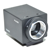
SECTION 11 CONNECTOR BOARD
11.1 Impedance selection
Standard input/output impedance for Pins 6, 7 and 9 of
12-pin connector is as follows:
TM-7 CN Option
Pin 6 Sync out TTL (OPEN) Open
Pin 7 Clock out Emitter follower 50Ω on R2
Pin 9 Vinit in Open R3 75Ω on R3
TM-7EX 75Ω-option S-option
Pin 6 Vinit in Open Open 75Ω R1 HD in
Pin 7 VD in 200Ω R2 75Ω R2 75Ω R2
Pin 9 HD in 200Ω R3 75Ω R3 Vinit(Open)
11.2 Jumper setting
TM-7CN TM-7EX S-0ption
W1 Short Open Open
W2 Short Open Open
W3 Open T side S side
W4 S side T.C side S side
W5 Open Open Short
W6 Open Short Short
W7 Open Short Open