5
Install wiring to the unit using a minimum of 18 inches of flexible conduit or cable attached to the
auto valve assembly in order to facilitate removal of the valve assembly from the reagent head
for cleaning or maintenance.
Wiring must conform to all applicable codes. Prior to pump startup; always check to ensure that the ADV
voltage and frequency matches that of the power supply. It is recommended that the ADV be powered
from a Ground Fault Circuit Interrupter (GFCI) protected electrical circuit.
1. Remove the enclosure front cover. Note: The plastic screw hole plugs can be pried out using a flat
bladed tool.
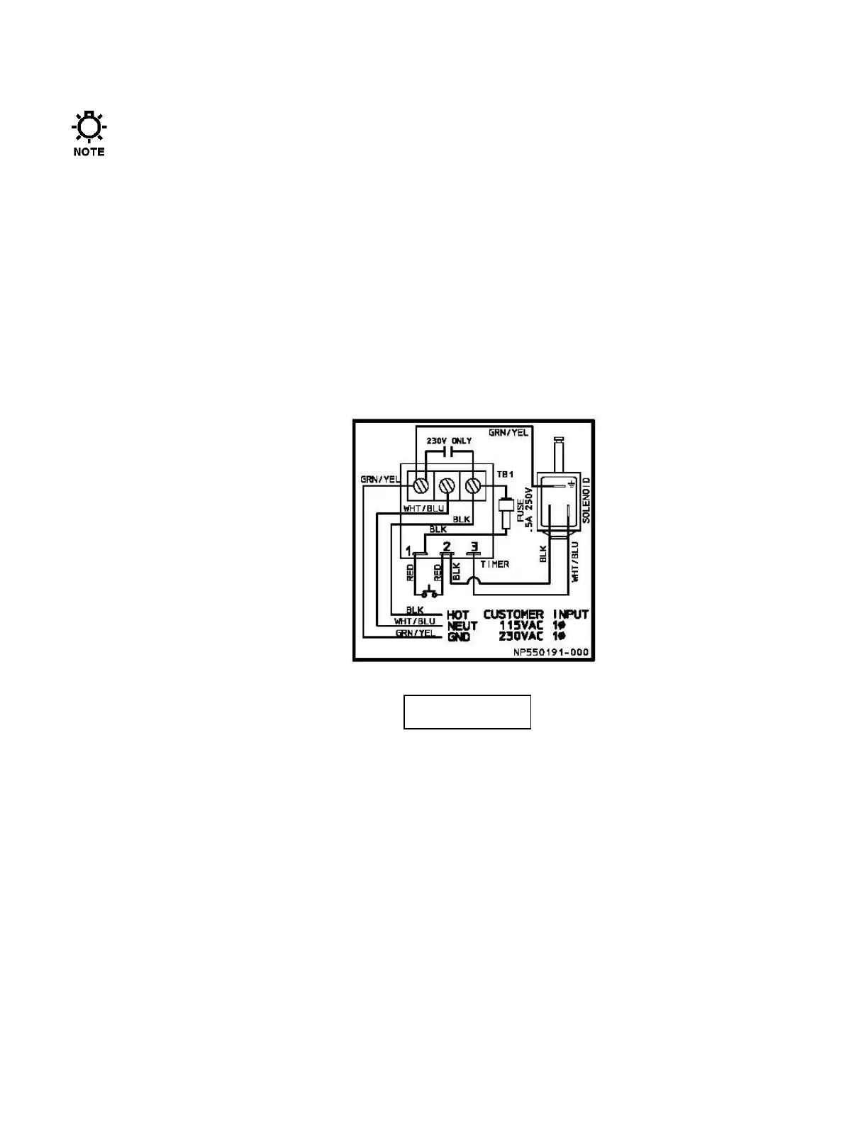
2. Bring AC power and ground wires into valve assembly enclosure through the 7/8” diameter hole in the
side of the enclosure. Use #20 AWG 105 degree C insulation wire size minimum. Connect per the
wiring diagram. The wiring diagram is also reproduced on a label affixed to the back of the enclosure
cover.
3. Apply power to the valve assembly with or without the pump running. Verify that the solenoid
mounted on the pump reagent head clicks every 30 seconds.
4. Reattach cover and replace plastic hole plugs over screws.