www.pulsar.pl EN54M RED POWER plus
5. Functions
5.1. Technical outputs.
The power supply is fitted with relay indication outputs changing state upon the occurrence of a specific
event.
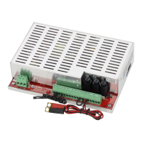
Fig. 5. Electrical diagram of relay outputs.
EPS - output indicating 230 V power loss.
The output indicates 230 V power loss. Under normal status – with the 230 V supply on, the output
is closed. In case of power failure, the PSU will switch the output into the open position after a time 10s.
Fig. 6. EPS technical output.
CAUTION! In Fig. the set of contacts shows a potential-free status of the relay, which corresponds to
power supply failure.
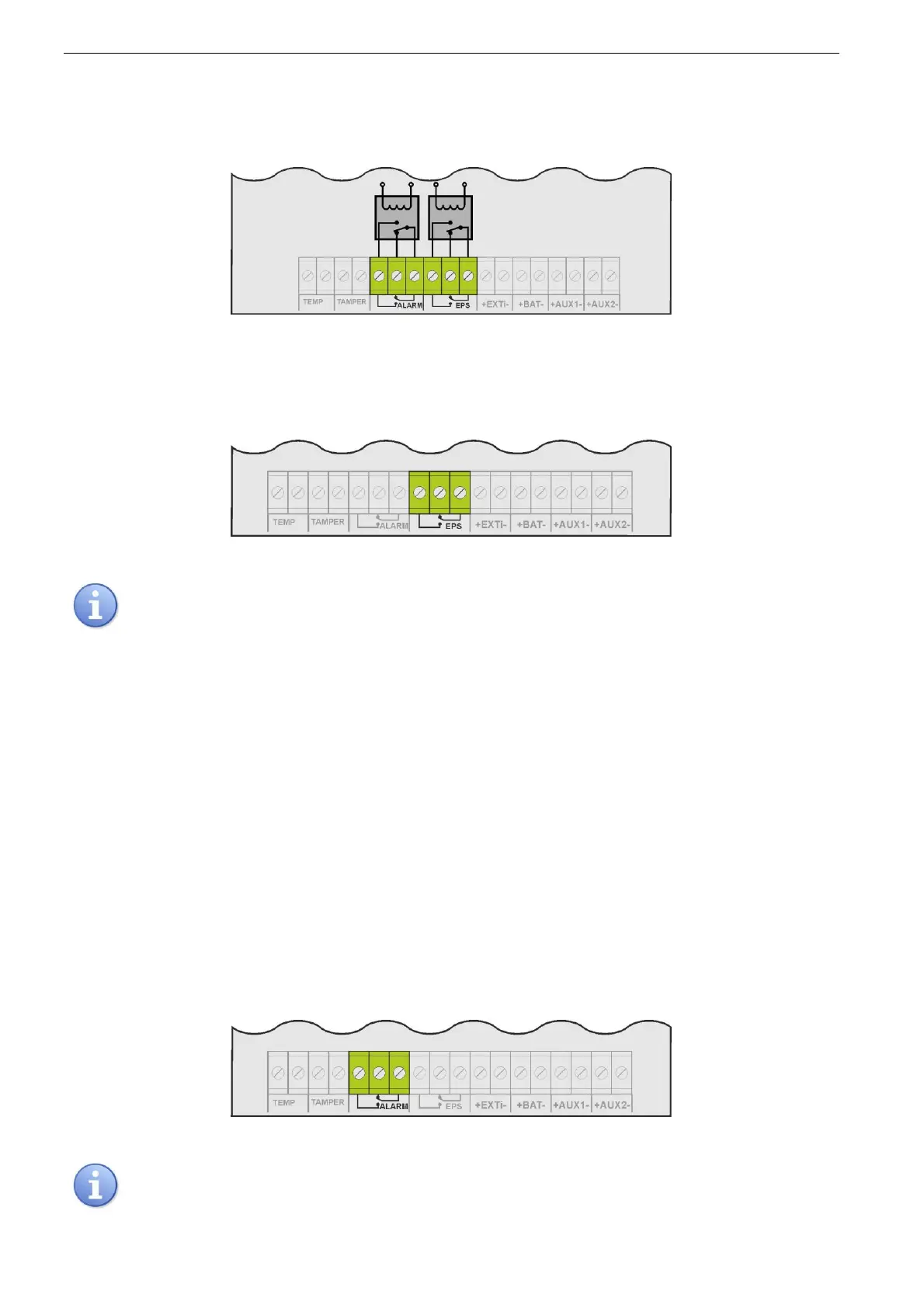
ALARM - technical output of collective failure indication.
Output indicating collective failure. In the case of 230 V power failure, battery circuit failure, PSU
failure, or EXTi input activation, the collective failure signal ALARM will be generated.
Failure can be triggered by the following events:
- AC power loss
- faulty batteries
- undercharged batteries
- disconnected batteries
- high resistance of the battery circuit
- no continuity in the battery circuit
- U
AUX1, AUX2
output voltage below 26 V
- U
AUX1, AUX2
output voltage over 29,2 V
- battery charging circuit failure
- blown F
AUX1
or F
AUX2
fuse
- PSU overload
- to high battery temperature (>65°C)
- temperature sensor failure, t < -20°C or t > 80°C
- enclosure opening - TAMPER
- internal damage of the PSU
Fig. 7. Technical output ALARM.
CAUTION! In Fig. the set of contacts shows a potential-free status of the relay, which corresponds to
power supply failure.
 Loading...