www.pulsar.pl EN54M RED POWER plus
3.3. Description of components and power supply terminals.
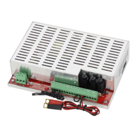
Table 1. Elements of the PSU module (Fig. 2).
L-N-PE 230 V power connector with protective terminal
Terminals:
TEMP – input of the battery temperature sensor
TAMPER – input of the microswitch tamper
Closed input = no indication
Open input = alarm
ALARM – technical output of collective failure of the PSU - relay type
EPS – technical output of AC power failure indication
open = AC power failure
closed = AC power - O.K.
EXTi – external failure input
Closed input = no indication
Open input = alarm
+BAT- – terminals for connecting the battery
+AUX1- – AUX1 power output ( - AUX=GND)
+AUX2- – AUX2 power output ( - AUX=GND)
CAUTION! In Fig.2 the set of contacts shows a potential-free status of the relay, which corresponds to
power supply failure.
Fuses:
F
BAT
– fuse in the battery circuit,
F
AUX1
– fuse in the AUX1 output circuit,
F
AUX2
– fuse in the AUX2 output circuit,
The fuse values are given in table 4 - "Electrical parameters".
LEDs – optical indication:
230 V – voltage in the 230 V circuit
APS – battery failure
ALARM – collective failure
AUX1 – AUX1 output voltage (at the AUX1 connector)
AUX2 – AUX2 output voltage (at the AUX2 connector)
PANEL LED – the EN54M-LED external optical indication panel
Battery temperature sensor
Battery connectors; positive: +BAT = red, negative: - BAT = black
Fig. 2. View of the PSU module.

 Loading...