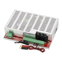
www.pulsar.pl EN54M RED POWER plus
7. Technical parameters.
Electrical parameters (Table 4).
Mechanical parameters (Table 5).
Safety of use (Table 6).
Recommended types and sections of installation cables (Table 7).
Table 4. Electrical parameters.
Functional class EN 12101-10:2007
22 V÷ 27,6 V DC – buffer operation
20 V÷ 27,6 V DC – battery-assisted operation
Continuous output current Imax a
Instantaneous output current Imax b
(5 min)
Maximal resistance of the battery circuit
Current consumption by the PSU
during battery-assisted operation
Coefficient of temperature compensation
of the battery voltage
-36mV/ ºC (-5 ºC ÷ 40 ºC)
The LoB low battery voltage indication
Ubat < 23 V, during battery mode
Overvoltage protection OVP
U>32 V±2 V, automatic recovery
Short-circuit protection SCP
- F
AUX1
, F
AUX2
melting fuse (failure requires fuse replacement)
105-150% of power supply, automatic recovery
Battery circuit protection SCP and reverse
polarity connection
- F
BAT
melting fuse (failure requires fuse replacement)
Deep discharge battery protection UVP
U<20 V (± 2%) – disconnection of the batteries
Technical outputs:
- EPS FLT; indicating AC power failure
- ALARM; indicating collective failure
- relay type: 1 A@ 30 V DC /50 V AC
- 10s time lag.
- relay type: 1 A@ 30 V DC /50 V AC
Technical inputs:
- EXTi; external failure input
- TAMPER; input of the microswitch
tamper
Closed input – no indication
Open input - alarm
Closed input – no indication
Open input - alarm
- LEDs on the PCB of the power supply unit (see section 3.3)
Fuses: - F
BAT
- F
AUX1
- F
AUX2
F 5 A/250 V
F 4 A/250 V
F 4 A/250 V
F 6,3 A/250 V
F 5 A/250 V
F 5 A/250 V
F 10 A/250 V
F 6,3 A/250 V
F 6,3 A/250 V
F 12,5 A/250 V
F 10 A/250 V
F 10 A/250 V
Additional equipment
(not included)
- fuse modules: EN54C-LB4, EN54C-LB8
- sequential modules: EN54C-LS4, EN54C-LS8
- the EN54M-LED external optical indication panel
- bracket EN54M-DIN1

 Loading...