EasyManua.ls Logo

Pulsar IMP - User Manual

Pulsar IMP
2 pages
To Next Page IconTo Next Page
Loading...
LIQUIDS and SOLIDS
Mount the IMP away from any obstructions, falling
water/solids, rough walls, pumps, switches, etc…
Visualize looking down the echo path of the IMP and
seeing a nice clear shot (2’+ dia.) to the very bottom
during fill and empty cycles.
Ensure the maximum level does not come within the
minimum blanking distance.
Confirm the inside of the standpipe is smooth and does
not have any protrusions at the weld.
Increase the blanking distance 2+ inches beyond the
end of the standpipe where it attaches to the vessel.
Typically, mount the IMP 1/2 the tank radius.
Be careful screwing the IMP into a NPT thread and do
not over-tighten.
(Call Pulsar Technical Support for Special Service
Passcode and Instructions 850-609-1777.)
MOUNTING
Do not over-tighten the threads! Try loosening if level is
reading very high.
LIQUIDS
Dome top tanks will require First Echo Algorithm.
If reading false level, use P21 and set true distance.
SOLIDS
Consult factory if the silo is dusty—we may need to up-
grade to a stronger system.
If reading false level, use P21 and set true distance.
If acoustically noisy, change to Largest Echo Algorithm.
IMP PC SOFTWARE
Warning… in 2-wire mode, inserting the RS232 cable will
result in automatic 20mA output.
Pulsar, Inc., PO Box 799, Shalimar, FL 32579 Phone: (850) 609-1777 Fax: (850) 651-4777 support@pulsar-us.com
IMP INSTALLATION TROUBLESHOOTING
ESC
(Display invert)
UP
(Temperature)
Down
(Echo Strength)
Enter
(Loop Current mA)
Congratulations on your purchase of a
Pulsar IMP - the low cost integral solution!
This quality system has been developed with the
latest digital ultrasonic technology for liquids,
slurries, and solids. No more noise and beam
angle problems. Also, no handheld programmer
or software required.
It provides non-contacting level and volume
measurement with 2 user-defined relays. Comes
standard as both 2-wire and 3-wire configuration.
Intrinsically Safe loop powered version available
with ATEX approval for hazardous areas.
IMP WIRING
2– wire (I.S. version must use barrier) 3– wire (relays can be used)
Pulsar Quick Start Manual - IMP
3– wire (rarely used as source)
Question and Answer IconNeed help?

Do you have a question about the Pulsar IMP and is the answer not in the manual?

Pulsar IMP Specifications

General IconGeneral
Resolution1 mm (0.04 in)
Operating Temperature-40 to +80°C (-40 to +176°F)
Output4-20 mA / HART
Process Connection1" NPT
Wetted MaterialsPTFE
Storage Temperature-40°C to +80°C (-40°F to +176°F)
Humidity Range0 to 100% RH
DimensionsVaries by model
WeightVaries by model
DisplayLCD
Protection RatingIP68

Summary

IMP INSTALLATION

LIQUIDS and SOLIDS

Mounting guidelines for liquids and solids, including obstruction avoidance and blanking distance.

TROUBLESHOOTING AND SUPPORT

General Troubleshooting

Covers mounting tips, liquid/solid application issues, and PC software warnings.

IMP WIRING CONFIGURATIONS

2-wire and 3-wire Diagrams

Wiring diagrams for 2-wire (I.S.) and 3-wire (relays/source) modes.

PROGRAMMING THE IMP

Enter Program Mode

Procedure to enter programming mode using passcodes like 1997.

Choose APP (Application) Settings

Selecting application parameters like mode, units, empty level, span, and blanking distances.

Calibration and Run Mode

Final calibration step and entering the device into run mode.

PROGRAMMING RELAYS

Relay Configuration Parameters

Details on configuring relay type, function, and setpoints for alarm or control.

TROUBLESHOOT FALSE ECHO

False Echo Mapping Procedure

Procedure to address false echoes by setting true distance and mapping echoes.

IMP PC SOFTWARE FUNCTIONALITY

Echo Profile Analysis

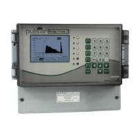
Screenshot and description of the IMP PC software for analyzing echo profiles.

Related product manuals