www.PyleUSA.com
6
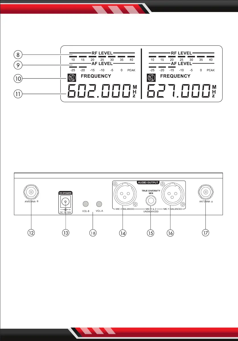
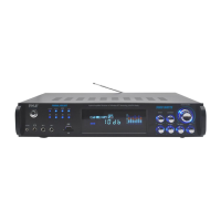
LCD PANEL:
After turning ON the “POWER”, LCD screen will display the following:
8. RADIO FREQUENCY LEVEL: Strength indicator of radio signal.
9. AUDIO FREQUENCY LEVEL: Strength indicator of incoming audio signal.
10. MUTE: Indicates if microphone is powered o.
11. FREQUENCY & CHANNEL: Displays current frequency and channel.
REAR PANEL:
12. ANTENNA-B: Connect the antenna to the BNC socket.
13. POWER SUPPLY: For power adapter with DC12~18V 500mA.
14. MIC 2 BALANCED OUTPUT: Balanced XLR audio output.
15. MIXED OUTPUT: Unbalanced 1/4" audio output for MIC 1 & MIC 2.
16. MIC 1 BALANCED OUTPUT: Balanced XLR audio output.
17. ANTENNA-A: Connect the antenne to the BNC socket.
18. VOL-A, VOL-B: Control the microphone- A or channel -B volume