www.qimaging.com ©2014 QImaging. All rights reserved. QI_OPTIMOS_UM_Rev_A0
24
optiMOS USER MANUAL
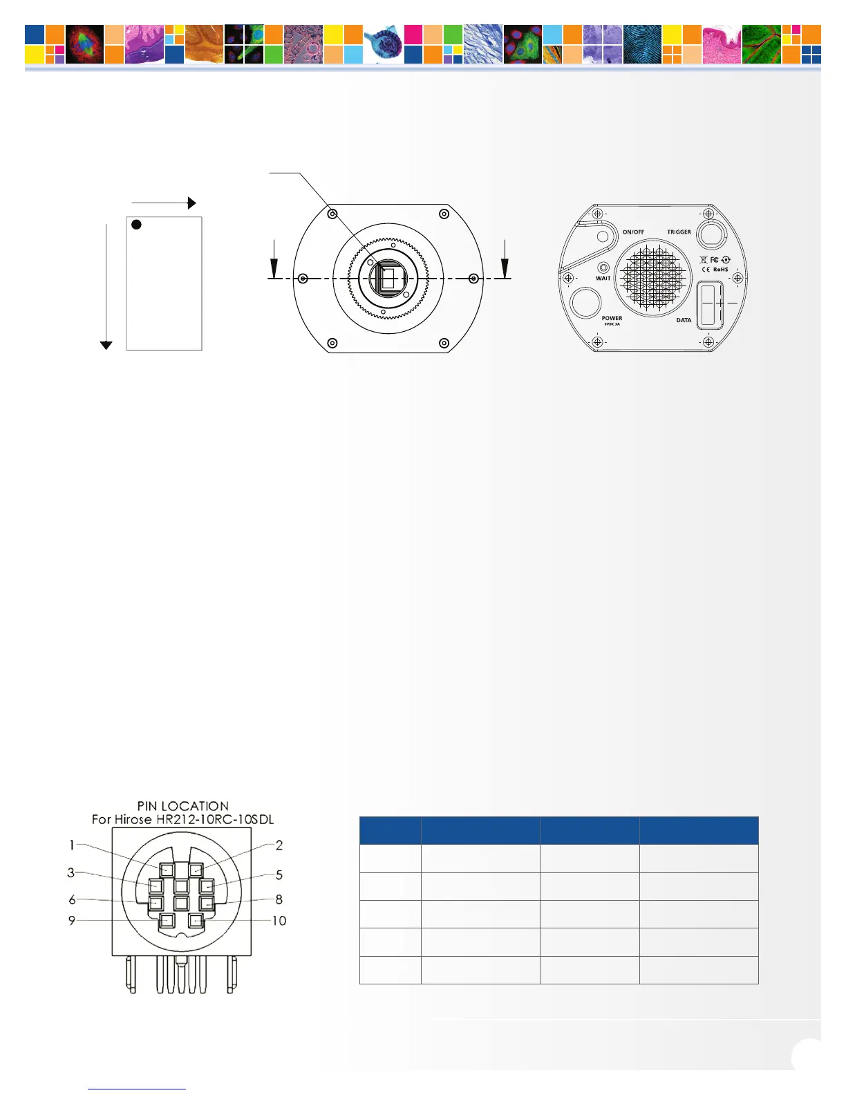
Sensor Orientation
When the optiMOS is coupled to the side port of an inverted microscope with the flat surface of the camera
parallel to the table, the sensor orientation will match the view seen through the eyepiece. This allows for easy
access to the mounting holes to stabilize the camera while maintaining a consistent perspective between the
captured images and what’s seen down the eyepiece of the microscope.
For the top port of upright microscopes and bottom ports to some inverted microscopes, the optiMOS must
be rotated 90° counter-clockwise to match the view seen through the eyepiece. This is due to the differences in
the optical paths between inverted side ports and upright top ports.
I/O Connector Pinout
The I/O (Input/Output Status) connector provides information about trigger function, DAC, and TTL signals.
Inputs must be at least 3.15 V for a high and less than 0.9 V for a low.
The numbers on the I/O connector diagram correspond to the numbers given to the definition of each of
the pins.
The I/O trigger cable connects to Hirose connector HR212-10RC-10SDL(74) on the back of the camera. Below
is a description of each of the trigger pins:
Pin # Signal Pin # Signal
1 Trigger In 6 Trigger Ready Out
2 Expose Out 7 Spare Output
3 Spare Output 8 Spare Input
4 Spare Output 9 Power Ready
5 Spare Input 10 Ground
(0,0)
y=1080
x=1920
A A
(0,0)
(BOTTOM)
(TOP)