30
BEGIN INSTALLATION
A
Reference both Sample of Wiring Configuration (A)
and Detailed Wiring Configuration (A)
(on next page).
1. Connect an 18 gauge wire to Power Source—find best
routing, mark it and run wire to QUANTUM® location (A).
The QUANTUM® requires a continuous power
source of 15 Amps at 11-15 VDC or 10 Amps at 22-28
VDC. If a continuous power source is not available, a
DC to DC converter MUST be used.
2. Connect a 22 gauge wire to Park Brake and Ignition
Switch—find best routing, mark it and run wire to
QUANTUM® location (A).
3. Connect a 22 gauge wire to Driver Interface—find best
routing, mark it and run wire to QUANTUM® location (A).
4. Connect a 22 gauge wire to Occupant Interface—find best
routing, mark it and run wire to QUANTUM® location (A).
5. Install the Driver Interface (Master Switch and Occupant
Switch) near or on the driver’s console (A) and connect the
switch to the harness.
6. Install the Occupant Interface underneath thin flip-up
theatre seats or wall next to the QUANTUM® (A) and connect
switch to harness.
Occupant Interface MUST be mounted where it’s
easily accessible to the occupant.
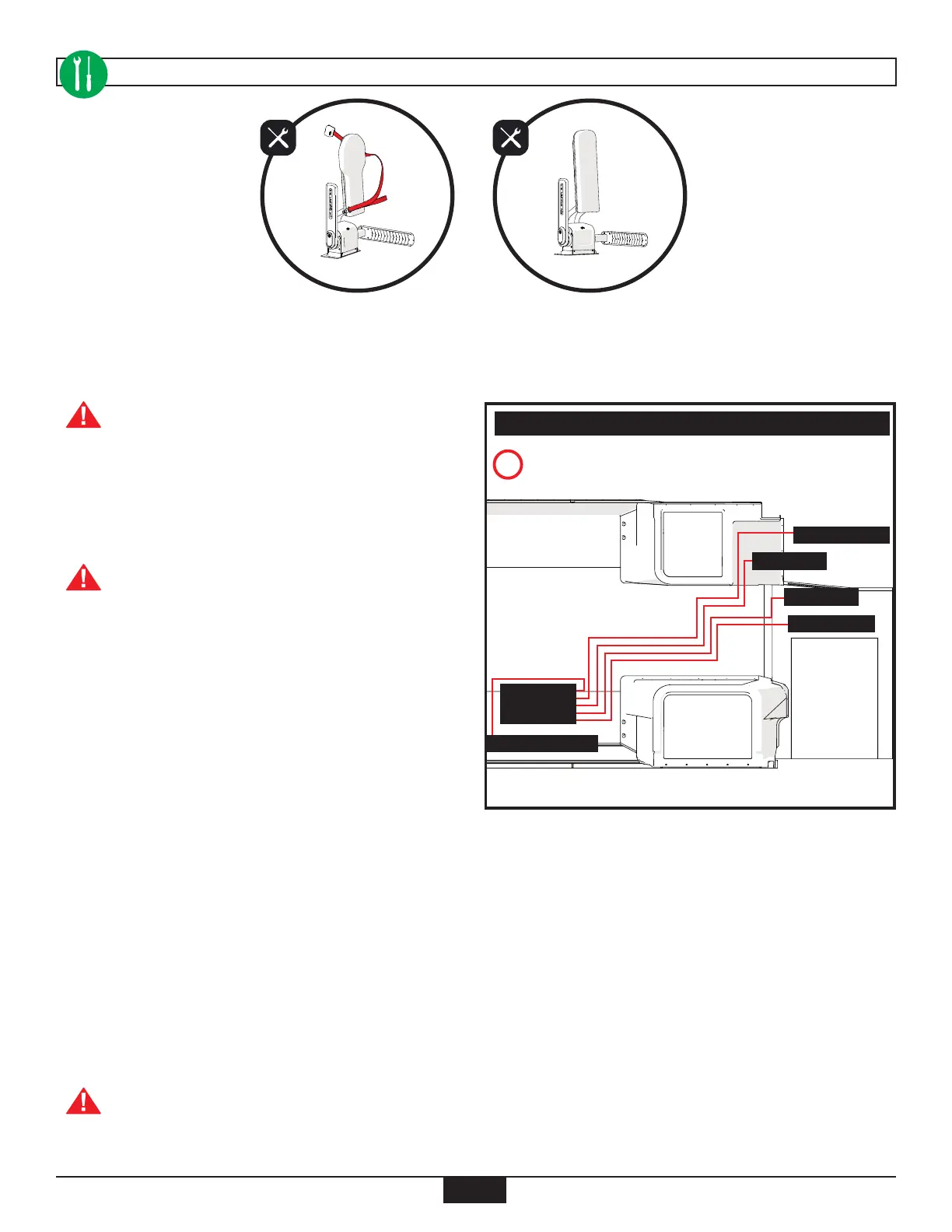
Installed QUANTUM® Securement System – (US)
OR
Installed QUANTUM® Securement System – (CA and UK)
SAMPLE OF WIRING CONFIGURATION
Driver Interface
Park Brake
Power Source
Occupant Interface
Ignition
QUANTUM