Chapter 2
2 -
1
Chapter 2
Connector Configuration
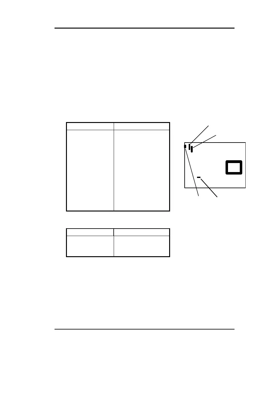
This section lists all connector pin assignments and port description on
the mainboard. The situations of the connectors and ports are illustrated
in the following figures. Before inserting these connectors, please pay
attention to the directions.
2.1 Power Connector (J3)
PIN NUMBER FUNCTION
1 POWER GOOD
2 +5V
3 +12V
4 -12V
5 GND
6 GND
7 GND
8 GND
9 -5V
10 +5V
11 +5V
12 +5V
2.2 Modem Ring on Connector (JP23)
PIN NUMBER FUNCTION
1 GND
2 INST-ON
3 5VSB
2.3 ATX Power Connector (PW2)
2.4 Power Switch (JP20)
J3
JP23
CPU
PW2
JP3
 Loading...