– 10 –
5. DO ensure the blade is mounted with the
rotation arrow in the proper direction and is
securely tightened with a wrench.
6. DO wear proper safety equipment at all times
when operating the saw. Wear goggles and
dust mask at all times when operating saw.
7. DO periodically check the blade for cracks or
bond fatigue.
8. DO ensure that blade is traveling through
water reservoir for wet cutting.
9. DO NOT operate the saw without all safety
guards in position.
10. DO NOT operate the saw with blades larger
or smaller than recommended.
11. DO NOT cut dry with blades marked
“Use Wet.”
12. DO NOT exceed maximum RPMs
recommended by the blade manufacturer.
13. DO NOT force the material into the blade. Let
the blade cut at its own speed.
14. DO NOT cut material not recommended by
the blade manufacturer.
TROUBLESHOOTING
OVERHEATING OF SAW:
1. Turn saw off and let it rest until motor is cool
to the touch.
2. Check and clean the ventilation slots,
removing blockage and dirt.
THE SAW DOES NOT START:
1. Check that power cord is properly plugged in.
2. Check outlet power source and circuit
breaker.
3. Make sure yellow safety key is fully pushed
into switch.
WHAT TO DO WHEN THE
ALIGNMENT IS OFF ON THE 83200Q:
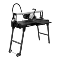
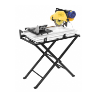
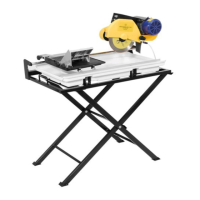
The 83200, 24” Bridge Saw motor or bridge does
not need to be squared up or aligned, since the
bridge does not allow the saw motor to move.
When it appears that the saw is out of alignment,
it is the rip fence that needs to be squared up.
Tools needed:
24” Framing Square, Phillips Screw Driver and
¼” Nut Driver or Pliers
The following steps should be used to align the rip
fence for the 83200Q:
1. Pull the power unit towards you and lock in
place with the transport screw.
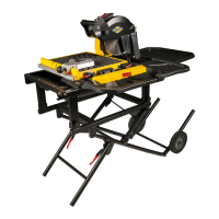
2. Once the power unit is secured, place the
Framing square firmly against the blade on the
left side of the cutting surface. The square must
be flush with the blade. (See Image A).
IMAGE A IMAGE B
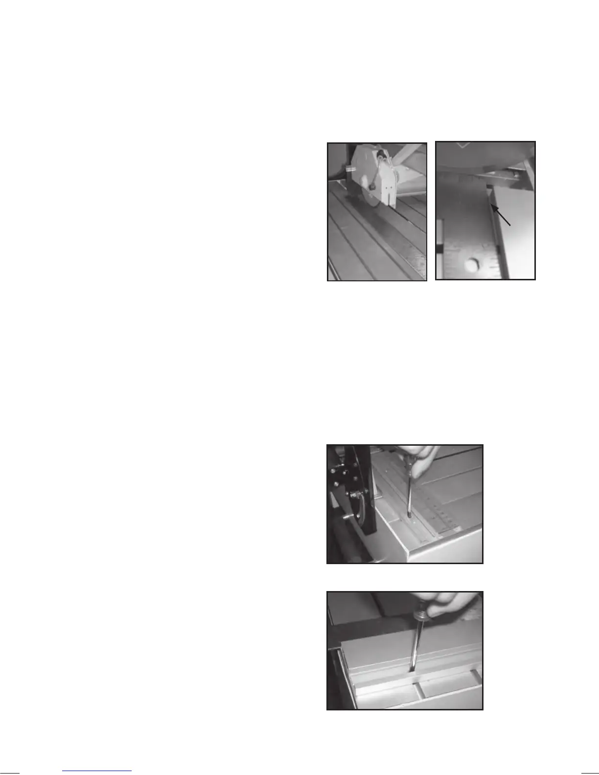
3. Slide the square into the rip fence, making sure
the square stays firmly against the blade. Look
for a gap between the square and the rip fence.
If there is a gap, adjustments will be necessary.
(See Image B)
4. To adjust the gap, first remove the Angle cutting
guide. This will expose two screws in the
aluminum track. Loosen both screws in the
extruded aluminum bar. (See Image C & D)
Rip
Fence
Gap
IMAGE C
IMAGE D
Right
Rip Fence
Left
Rip Fence
 Loading...