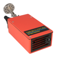
Atmospheric Oil Mist Detection System
MULTIPLEX
AM8/JANUARY 2015
EMAIL qmi@oilmist.com WEBSITE www.oilmist.com 4 East Barnet Road, London, England, EN4 8RW TEL +44 (0)20 7328 3121
Maintenance Part5-5
REPLACING FAN (Q1004) IN SENSOR
Remove lid by taking out the four countersunk Allen screws using 2.5mm Allen key
(Q1007).
Remove RED and BLACK wires from fan failure terminal block.
Remove four buttonhead Allen screws holding fan to air sensor using 2.5mm Allen
key.
Fit new fan by replacing four buttonhead Allen screws. Check direction arrows on
fan.
Fit RED wire to the + terminal of fan failure terminal block.
Fit BLACK wire to the - terminal of fan failure terminal block.
ADJUSTING FAN FAILURE ON Q10 - FH FAN
WARNING: Any attempt to adjust other components on the circuit board will
invalidate the guarantee and may stop the sensor working.
1. Turn the potentiometer screw fully anti - clockwise (15 turns).
2. Connect air sensor to Monitor. The LED on the front of the air sensor will flash
GREEN.
3. Allow 2 minutes before adjusting, by this time the LED should be AMBER with a
RED pulse.
4. Slowly turn the potentiometer clockwise until the LED turns to a steady GREEN.
5. When the LED is showing steady GREEN, turn the same potentiometer a further
quarter turn clockwise.
6. Test for fan failure operation by gently stopping the fan with your finger.
7. Check that the LED flashes RED.
8. Refit Sensor lid using the four countersunk Allen screws, ensuring red and black
wires are not trapped.
9. Wait for two minutes and ensure LED remains constant GREEN.
10. Installation of the Q1004 fan is now complete. Refit Sensor in chosen position.
+
_
an
ailure LED
fan failure terminal block
adjustment
potentiometer
fa
circuit board