QM_XC7A35T_SDRAM Core Board User Manual V02
2.2.2 QM_XC7A35T_SDRAM SPI Boot
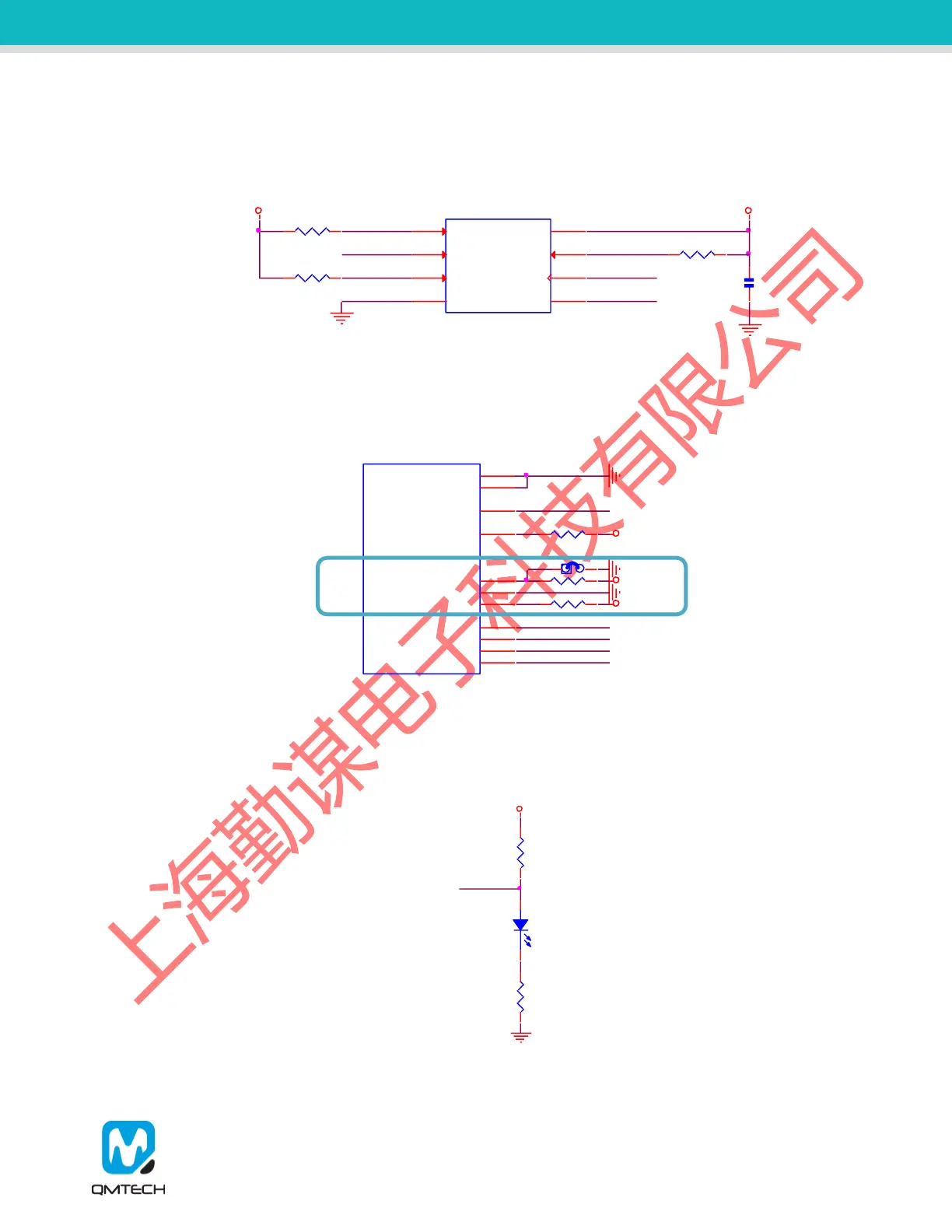
In default, QM_XC7A35T boots from external SPI Flash, detailed hardware design is shown in below figure.
The SPI flash is using N25Q064 manufactured by Micron, with 64Mbit memory storage.
Figure 2-6. SPI Flash
The FPGA boot sequence setting M0:M1:M2 is configured as 1:0:0 which indicates FPGA will boot from SPI
Flash after power on. In default, the jumper J1 is under closed status.
Figure 2-7. M0:M1 Hardware Settings
The LED D2 will be turned on after the FPGA successfully loading configuration file from SPI Flash during
power on stage. In this case, LED D2 could be used as FPGA loading status indicator.
Figure 2-8. FPGA_DONE Status Indicator
FPGA_DQ1 FPGA_DQ3
FPGA_CCLK
FPGA_DQ0
FPGA_DQ2
U2
N25Q064A13ESE40F
nCE
1
SIO3
7
SO/SIO1
2
VSS
4
SI/SIO0
5
SCK
6
SIO2
3
VDD
8
C33
100nF
3V3
R154.7K
FPGA_CSO_B
3V3
R2334.7K
R2344.7K
TMS
TCK
TDI
TDO
FPGA_DONE
PROG_B
R229 4.7K
3V3
R230 1K
3V3
XC7A35T-FTG256
U9A
DONE_0
H10
DXP_0
K8
TCK_0
L7
DXN_0
K7
M0_0
M9
M1_0
M10
INIT_B_0
K10
TDI_0
N7
TDO_0
N8
M2_0
M11
PROGRAM_B_0
L9
TMS_0
M7
3V3
R231 1K
J1
R13
1K
D2
Red
1
2
3V3
R25
1K
FPGA_DONE