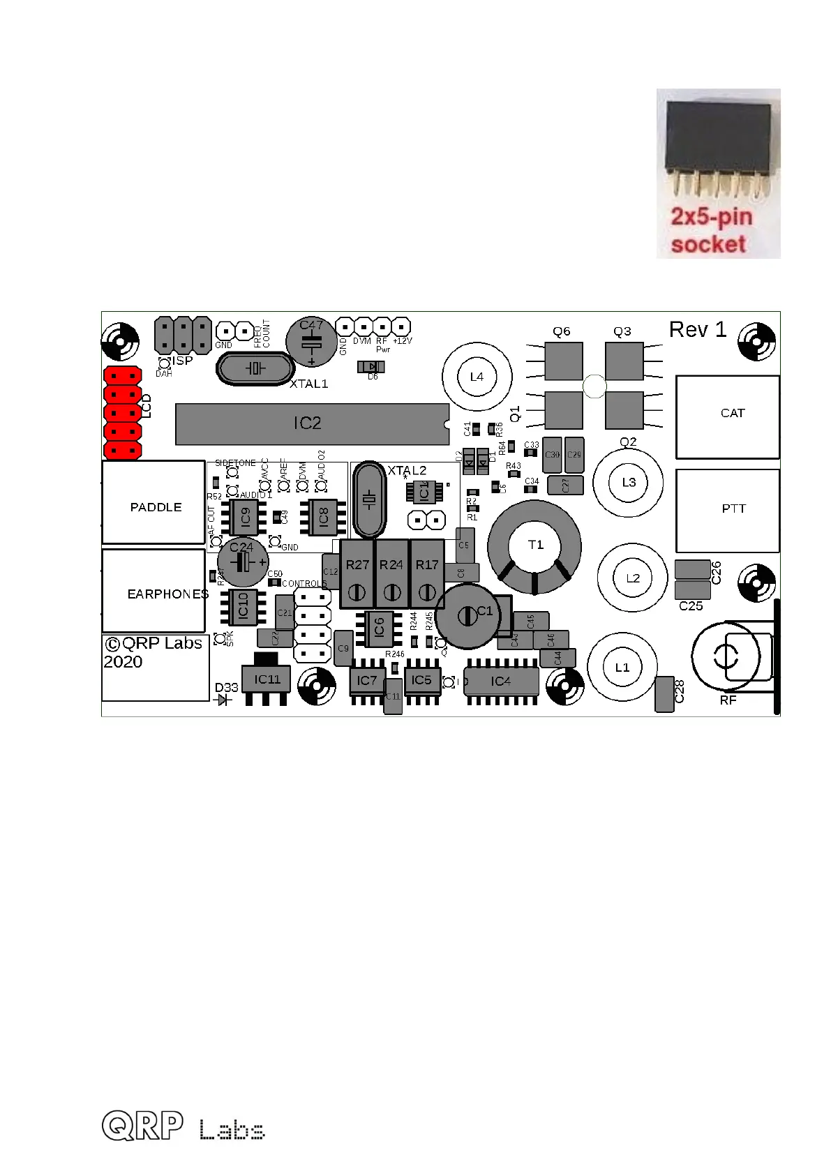
3.22 Install 2x5 LCD header
This female pin header (socket) connects the main QCX-mini PCB to the
display board above it. Solder one pin in place first and check that the
header is nicely seated on the PCB before soldering the other 9.
Be sure to install the 2x5-pin FEMALE pin header connector (see right),
not the male header connector which is installed on the LCD board.
Try to hold the socket as far towards the top side of the board (in the
diagram below) as possible, that is, as far away from the Paddle connector
as possible. This is because installing the earphones and paddle
connectors is a tight fit.
48
 Loading...

