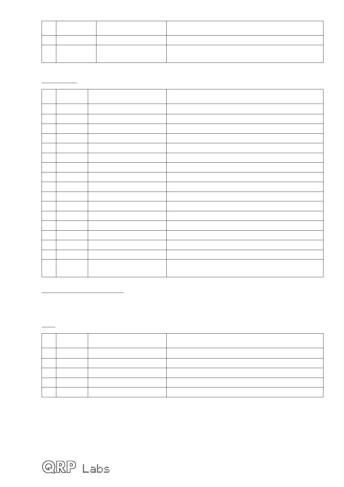
Qty Value Description Component numbers
1 5K Linear potentiometer R36 (on controls board)
1 22K Trimmer
potentiometer
R47 (on display board)
Capacitors (50V, Multi-layer Ceramic capacitors)
Qty Value Description Component numbers
5 1nF SMD C14, 16, 18, 23, 33
2 2.2nF SMD C19, 20
1 3.3nF SMD C53
4 10nF SMD C4, 7, 10, 42
1 33nF SMD C15
1 39nF SMD C17
1 47nF Label “473” C9
1 47nF SMD 13
2 0.1uF Label “104” C12, 29
14 0.1uF SMD C2, 3, 6, 32, 34-36, 39-41, 48-50, 52
5 0.47uF Label “474” C11, 43-46
2 1uF Label “105” C21, 22
2 2.2uF SMD C31, 100 (C100 on display board)
3 10uF SMD C37, 38, 51
2 470uF Electrolytic C24, 47
1 30pF Ceramic trimmer
capacitor
C1
Band-specific capacitors (50V, 5% capacitors which must be C0G/NP0 type)
Note: depending on band, some capacitors may be left over at the end. This is normal!
80m
Qty Value Description Component numbers
1 39pF Label “390” C5
1 22pF Label “220” C8
1 180pF Label “181” C30
2 470pF Label “471" C27, 28
2 1200pF Label “122” C25, 26
6
 Loading...

