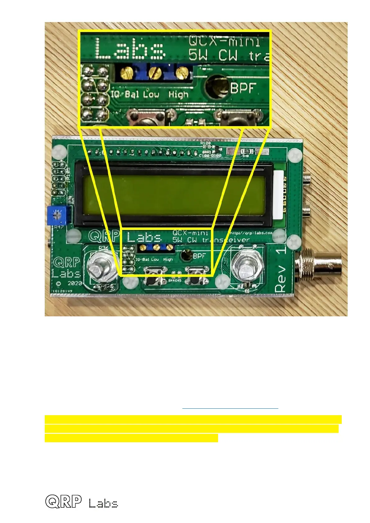
EasyManuals Logo

QRP Labs QCX-mini Assembly Instructions

Default Icon
121 pages
To Next Page IconTo Next Page
To Previous Page IconTo Previous Page
Page #73 background imageLoading...
Page #73 background image
In summary: the alignment tools built into the radio consist of a signal generator which
injects a signal into the RF front end, and digital signal processing which adds a 250-Hz
digital filter to the existing 200Hz analogue filter, and calculates the amplitude of the signal
detected in that bandwidth. During alignment, the amplitude is displayed on-screen as an
intuitive bar across the bottom row of the display. Using a screwdriver, you adjust the
trimmer component in order to maximize or minimize the displayed amplitude.
Unplug the antenna during alignment of the radio! Connect a 50-ohm dummy load
such as the QRP Labs dummy load kit http://qrp-labs.com/dummy
When using the TCXO module option, change menu item 8.5 Ref frq to 25,000,000. It
is critical to this before any further alignment. Enter the menu system as described
below, and turn to menu 8.5, edit it to 25,000,000.
 73

Table of Contents

Other manuals for QRP Labs QCX-mini

Questions and Answers:

Question and Answer IconNeed help?

Do you have a question about the QRP Labs QCX-mini and is the answer not in the manual?

QRP Labs QCX-mini Specifications

General IconGeneral
BrandQRP Labs
ModelQCX-mini
CategoryTransceiver
LanguageEnglish

Related product manuals