Do you have a question about the QSC ISA 300T and is the answer not in the manual?
Summarizes critical safety warnings regarding electric shock, rain, and moisture.
Details the meaning of warning symbols like lightning flash and exclamation point.
Provides the FCC compliance statement for the device.
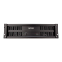
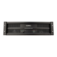
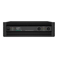
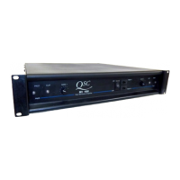
Describes the front panel controls and indicators of the ISA amplifiers.
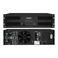
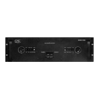
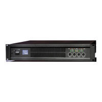
Illustrates and labels the rear panel components for different ISA models.
Explains how to operate the front panel power switch and related LED behavior.
Details the importance of keeping air vents clear for proper cooling.
Explains the meaning and behavior of POWER, SIGNAL, and CLIP LEDs.
Details the location and operation of the rear panel gain controls.
Explains the function and use of the DataPort V2 connector.
How to configure and use Stereo and Parallel operating modes.
Details DIP switch configurations for Stereo and Parallel modes.
Explains Bridge mode operation and its DIP switch settings.
Details the low frequency filter and its DIP switch configurations.
Displays frequency response graphs for various amplifier models.
Explains the clip limiter and its DIP switch settings.
Provides instructions and dimensions for rack mounting the amplifier.
Details cooling needs and how to connect AC power.
Explains how to connect using XLR and terminal block inputs.
Details connecting inputs via the DataPort V2 connector.
Instructions for using the screw terminal output connections.
Details connecting low impedance (2-16 ohm) loads to outputs.
How to connect Hi-Z loads in 25V, 70V, 100V for Stereo/Parallel modes.
Connecting Hi-Z loads in 140V and 200V for Bridge mode.
Guidelines for sharing power between Hi-Z and Lo-Z outputs on "T" models.
Instructions for securing output wiring to the chassis for reliability.
Provides general application information and principles for ISA amplifiers.
Explains principles of distributed line audio systems for "T" models.
Details LPF for 70-100V systems and distributed output examples.
Shows examples of 70V and 100V distributed output configurations.
Explains how to connect multiple low impedance loads in series.
Explains how to connect multiple low impedance loads in parallel.
Lists QSC DataPort-compatible products that interface with ISA amplifiers.
Provides solutions for problems where the amplifier produces no sound.
Addresses common audio problems like distortion, hum, hiss, and feedback.
Details amplifier protection features, cooling methods, and front panel indicators.
Outlines connector types, load protection, and output circuit types.
Details power consumption figures and control interfaces.
Lists the physical dimensions and weight of the amplifiers.
Lists output power ratings and impedance details for all models.
Details dynamic headroom, distortion, frequency response, and SNR.
Provides specific current consumption figures for various operating levels.
Provides QSC's mailing address, phone numbers, and web contact info.
| Type | Power Amplifier |
|---|---|
| Channels | 2 |
| 8 Ohm Stereo | 300 W |
| 8 Ohm Bridged | 900 W |
| THD | < 0.05% |
| Signal to Noise Ratio | > 100 dB |
| Voltage Gain | 32 dB |
| Total Harmonic Distortion | < 0.05% |
| Rack Units | 2U |
| Frequency Response | 20 Hz - 20 kHz |
| Input Impedance | 20kΩ balanced, 10kΩ unbalanced |
| Cooling | Convection |
| Dimensions | 19" x 3.5" x 15.5" |
| Power Requirements | 100-240 VAC |
| Weight (kg) | 10 |