15
TD-001517-01
K.2 Series Service Manual
Input/DSP board
The input section consists of three separate inputs (MIC/LINE, LINE/INST, and AUX STEREO) which are summed together
before entering an audio codec that transmits the digitized audio to the DSP. The integrated DSP is configured to process
the incoming audio signal and finely tune it (low/high pass filtering, EQ, limiting, compression, and more) before outputting
the signal(s) to the amplifier stages. Due to this tuning, the K8.2, K10.2, and K12.2 amplifier modules cannot be inter-
changed between each other unless their DSP firmwares are changed. There is also a microprocessor on the input/DSP
board which manages the LCD display, LEDs, buttons, and rotary encoder.
LCD board
The LCD board contains a monochrome display, microUSB connec-
tor, USB/I2C controller, rotary encoder, two navigational buttons, and
debouncer circuitry. The USB controller allows for communication over
the I2C bus between a computer and the microcontroller on the input/
DSP board. The rotary encoder and buttons are read by the microcon-
troller, so a debouncer circuit is implemented to reduce error. Physical
contacts can connect and disconnect multiple times during a button
push or release, so a debouncer circuit cleans up the inputs to the
microcontroller.
The LCD board is powered by the 3.3V rail, which originates on the
input/DSP board and comes into the LCD board at connector J1:pin4.
The 5V bus on the microUSB connector does not provide any power
to other circuits in the amplifier module, and is only monitored by the
USB/I2C controller.
DSP_RST_L
FAN_GND
AMP_SD_L
LEDS_ON
LINE_INST_SEL_N
MIC_LINE_SEL
2.5VREF MIX_OUT_P
MIX_OUT_N
MIX_OUT2_P
MIX_OUT2_N
LINE_INST_SEL_P
LEDS_ON_C
CS_L_DSP
TEMP_SENS
LCD_BACKLIGHT
SDA_I2C
SCL_I2C
TESTLCD_RST_L
CS_L_LCD
MOSI
SCLK
FAN_CTRL BTN2
BTN1
ENC_B
ENC_A
LCD_A0
SDA_I2C
CODEC_RST_L
SCL_I2C
CODEC_RST_L
SCLK
MOSI
AMP_SD_L
DOUBLER_RELAY
ACV_MON
FAN_CTRL
LIMIT_LED
MCLK
BICLK
LRCLK
SDTO
MOSI
SCLK
MISO
LEDS_ON_C
TEST FAN_GND
LF_CH_GND
HF_CH_GND
FRONT_LED
ACV_MONDOUBLER_RELAY
LF_CH_P
HF_CH_P
CODEC_CS_L
SDTI
DSP_RST_L
LINE_INST_SEL_P
CS_L_DSP
SWD_RST
SWD_DIO
SWD_CLK
CODEC_CS_L
MIC_LINE_SEL
LINE_INST_SEL_N
LCD_RST_L
LCD_A0
CS_L_LCD
FRONT_LED
REAR_LED
MOSI
SCLK
LEDS_ON
ACV_MON
MISO
MICROCONTROLLER
SDA_I2C
SCL_I2C
ENC_B
BTN1
MISO
ACV_MON
CODEC_RST_L
LEDS_ON
DSP_RST_L
SCLK
ENC_A
MOSI
REAR_LED
FRONT_LED
CS_L_LCD
LCD_A0
LCD_RST_L
LINE_INST_SEL_N
LINE_INST_SEL_P
MIC_LINE_SEL
CODEC_CS_L
LCD_BACKLIGHT
SWD_CLK
SWD_DIO
SWD_RST
CS_L_DSP
TEST
BTN2
DISPLAY_AND_GPIO
SDA_I2C
SCL_I2C
TEST
LCD_BACKLIGHT
LCD_RST_L
CS_L_LCD
MOSI
SCLK
FAN_CTRL BTN2
BTN1
ENC_B
ENC_A
LCD_A0
SWD_CLK
SWD_DIO
SWD_RST
TO_AND_FROM_AMP
FAN_GND
TEMP_SENS
HF_CH_P
LF_CH_P
DOUBLER_RELAY ACV_MON
FRONT_LED
HF_CH_GND
LF_CH_GND
AMP_SD_L
CODEC
MIX_OUT_P
MIX_OUT_N
MIX_OUT2_P
MIX_OUT2_N
LF_CH_P
HF_CH_P
CODEC_RST_L
CODEC_CS_L
LRCLK
BICLK
MCLK
SDTO
SDTI
MOSI
SCLK
HF_CH_GND
LF_CH_GND
DSP
FAN_GND
DSP_RST_L
TEST
LEDS_ON_C
TEMP_SENS
MISO
SDTI
SCLK
MOSI
SDTO
LRCLK
BICLK
MCLK
LIMIT_LEDCS_L_DSP
FAN_CTRL
ACV_MON
DOUBLER_RELAY
AMP_SD_L
INPUTS
AMP_SD_L
LEDS_ON
LINE_INST_SEL_N
MIC_LINE_SEL
2.5VREF MIX_OUT_P
MIX_OUT_N
MIX_OUT2_P
MIX_OUT2_N
LINE_INST_SEL_P
LEDS_ON_C
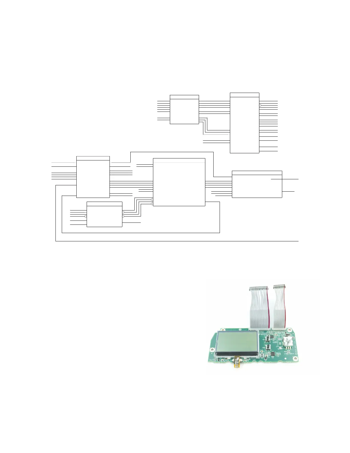
Figure 4.3.8 - Block diagram of the input/DSP board, showing the MCU, DSP, and Codec signals
Figure 4.3.9 - LCD board

 Loading...


