EN
12 (DRAFT 2017/05/02)
TD-000523-00-01-C
4. LIMITER LED – Illuminates (red) when the built-in limiter is activated to protect and avoid damage to the amplifier or
loudspeaker. If the signal level at any frequency is too high, or the amplifier is too hot, the limiter is activated and the
LED is illuminated.
5. POWER LED – Illuminates (blue) when power is applied to the unit and the ON/OFF switch is in the ON position.
NOTE: Unless the gain controls of all active inputs are set to 0 dB, the output signal from the MIX OUT (POST GAIN) will not
be at the same level as the input signal. If a “slave” speaker is intended to playback at the same level as the “master” speaker,
the gain control on the “slave” speaker should be set to0 dB.
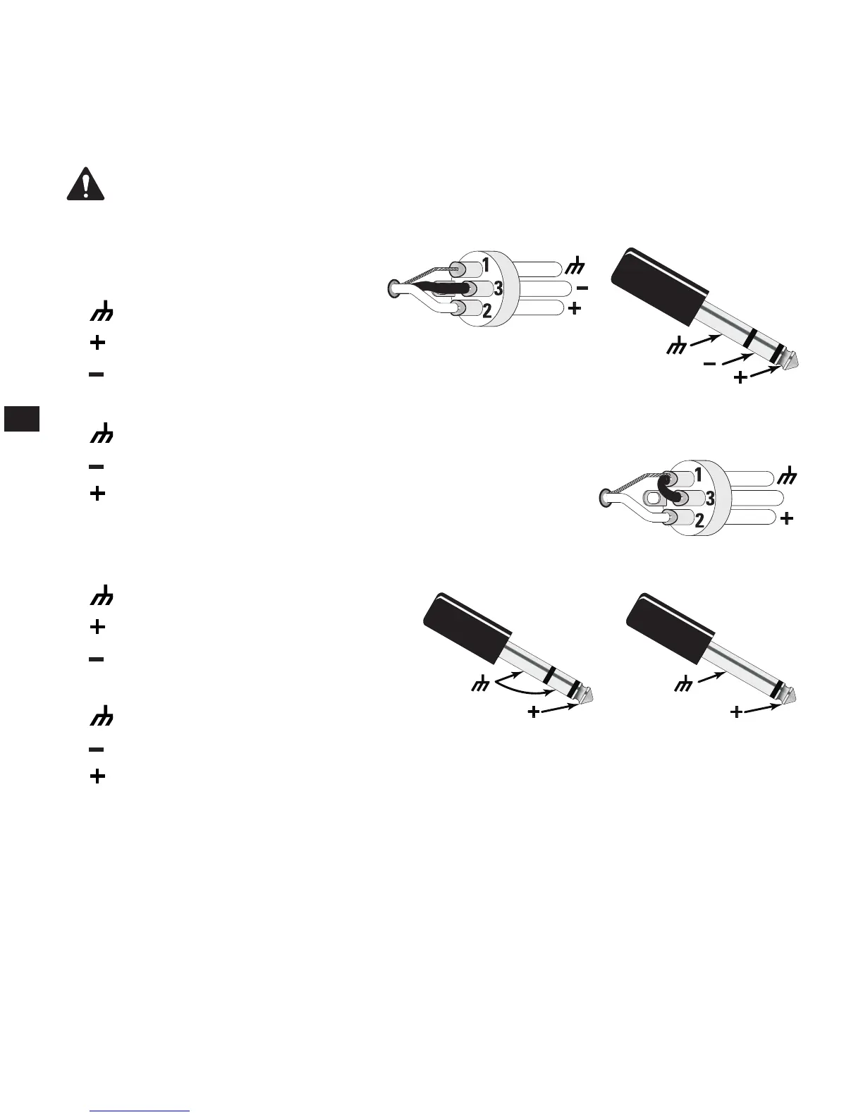
Balanced Inputs
Connect the XLR plug as shown in — Figure 13.
1. Shield (ground)
2. Positive
3. Negative
Connect the TRS plug as shown in — Figure 14. Do not use a TS 1/4” jack for balanced input.
1. Shield (ground)
2. Negative
3. Positive
Unbalanced Inputs
Connect the XLR plug as shown in — Figure 15. (Jumper pins 1 and 3.)
1. Shield (ground)
2. Positive
3. Negative
Connect the TRS or TS plug as shown in — Figure 16.
1. Shield (ground)
2. Negative
3. Positive
— Figure 13 —
— Figure 14 —
— Figure 15 —
— Figure 16 —