16
QSC Audio Products, LLC
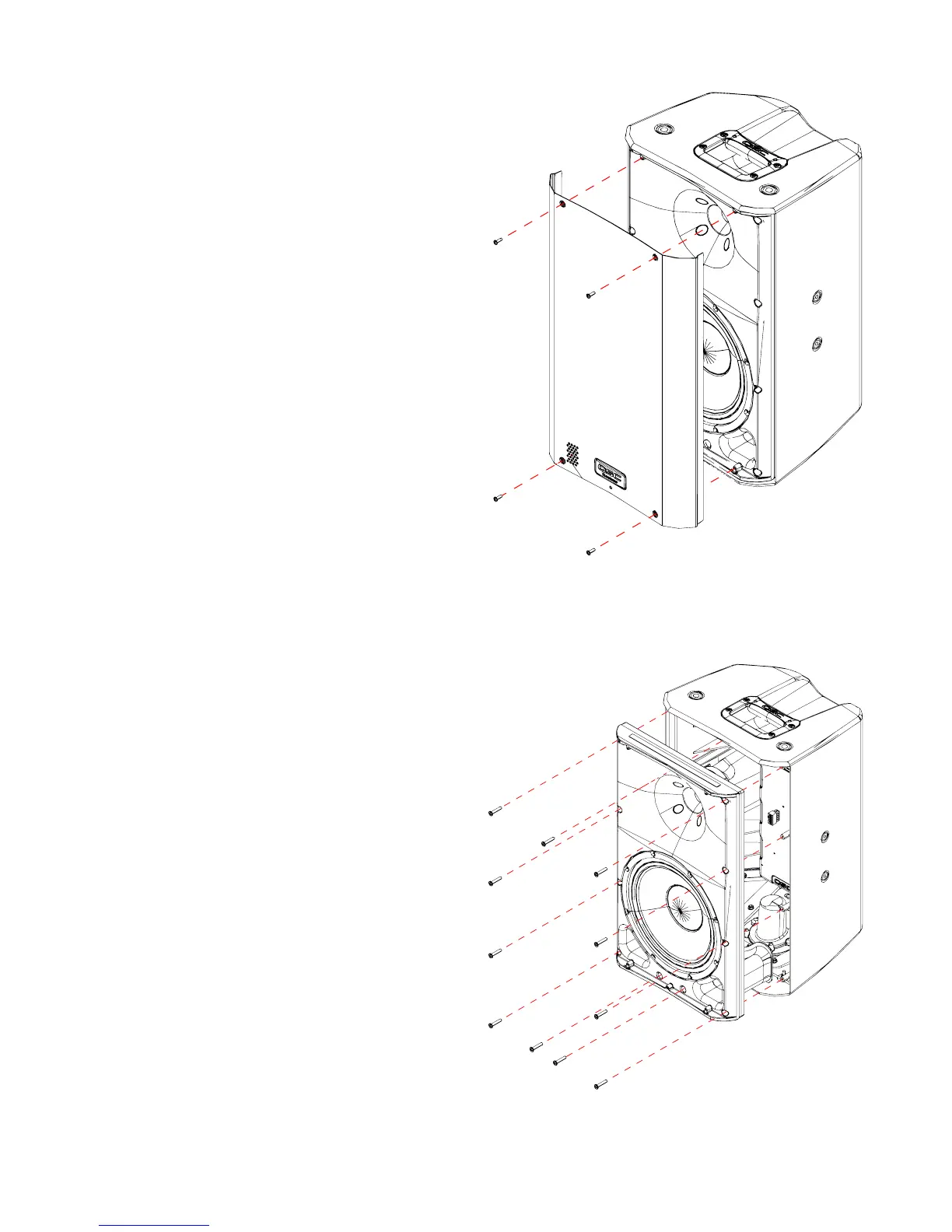
5.2 Front grille
Removal
1. Remove the four screws that attach the front grille to the
baffle.
2. Using a putty or butter knife, pry the grille outward and
remove it. If the grille is stuck, gently pry along the sides
in multiple locations until the grille becomes loose
enough to remove.
Installation
1. Verify that the gasket along the top and bottom of the
grille is still in place. If you are replacing the grille with a
new one, install new gasket along the top and bottom
of the grille to reduce vibrations between the grille and
baffle.
Note: Recommended gasket size is 1/2” width and at
least 1/16” thickness.
2. Fit the side edges of the grille in the space between the
baffle and enclosure. Press down gently. Be careful not
to bend the grille. If the grille does not fit in the space,
the baffle may need to be realigned.
3. Fasten the four screws that secure the grille to the baffle.
4. Use a rubber mallet with a large head to gently press in
the sides of the grille so that the grille is flush with the
enclosure.
5.3 Front baffle
Removal
1. To access the front baffle, the front grille must be
removed. Follow the instructions in “5.2 Front grille” on
page 16.
2. Remove all screws around the perimeter of the baffle.
3. Place the speaker on a work surface so that the baffle is
face-down.
4. Partially lift the enclosure away from the baffle assem-
bly.
5. Disconnect the molex connector from the BOP.
6. You may now fully remove the baffle assembly from the
main enclosure.
Installation
It’s recommend that the LF and HF transducers are installed
before reinstalling the baffle to the main enclosure assem-
bly.
1. Verify that the positive and negative terminals on the LF
and HF transducers are connected securely to the wiring
harness.
2. Verify that the gasket is properly installed around the
edge of the baffle.
3. Reinstall all acoustic insulation in both the main enclo-
sure assembly and baffle assembly.
Figure 5.3 - Front baffle removal
Figure 5.2 - Front grille removal

 Loading...


