+7(495) 797-3311 www.qtech.ru
Москва, Новозаводская ул., 18, стр. 1
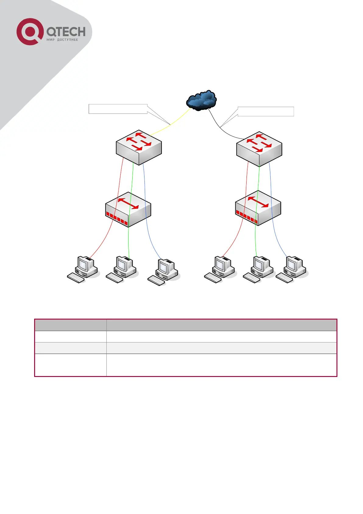
Ethernet1/1 of edge switch1. Contrarily, data traffic of userA, userB and userC will be
translated into VLAN1, VLAN2, VLAN3 by Ethernet1/1 of edge switch1 from network layer
respectively. In the same way, it implements multi-to-one translation for userD, userE and
userF on Ethernet1/1 of edge switch2.
UserA VID
=
1
UserB VID
=
2
UserC VID
=
3
UserD VID
=
1
UserE VID
=
2
UserF VID
=
3
User D,E,F VID=101
User A,B,C VID=100
UserA UserB UserC UserD UserE UserF
switch1
switch2
VLAN-translation typical application
Configuration Explanation
Downlink port 1/1 and uplink port 1/5 of Switch1 and Switch 2
Multi-to-One
VLAN-translation
Downlink port 1/1 of Switch1 and Switch2
Configuration procedure is as follows:
Switch1, Switch2:
switch(Config)# vlan 1-3;100
switch(Config-Ethernet1/1)#switchport mode trunk
switch(Config-Ethernet1/1)# vlan-translation n-to-1 1-3 to 100
switch(Config)#interface ethernet 1/5
switch(Config-Ethernet1/5)#switchport mode trunk
switch(Config-Ethernet1/5)#exit
 Loading...