QSW-4700 Series Switches Hardware Installation and Reference Guide
Appendix
72
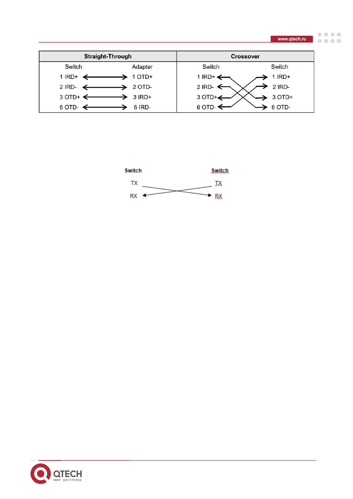
Figure 7-2 100BASE-TX/10BASE-T Connection
7.1.2. Fiber Connection
You can choose single mode or multimode fibers according to the module types. Figure 7–3
shows connection of fiber-optic cable.
Figure 7-3 Fiber-Optic Cable Connection
7.1.3. Lightening Protection
7.1.3.1. Installing AC Power Arrester (Lightning Protection Power Strip)
The AC power port must be connected to an external lightning protection power strip to prevent
the switch from being struck by lightning when the AC power cord is introduced from the outdoor
and directly connected to the power port of the switch. The lightning protection power strip can
be fixed on the rack, workbench, or wall in the equipment room by using cable ties and screws.
AC power enters the lightening protection power strip and then gets to the switch.
 Loading...