Description
Module Installation
Meet Stardust, a cosmic tape looper. Much like the cacophony of galaxies, supernovas, and stars we find
in our own celestial canvas, Stardust captures layers of audio to construct new sonic imagery, and finds
ways to take the esoteric, and make it concrète.
The foundation of Stardust is a stereo looper with all the essential controls to record and manipulate
sound, while supporting click-less looping transitions, an ultra-low noise floor, and high-fidelity audio hard-
ware. However, getting the perfect loop is only half of the equation - Stardust also focuses on the texture
and vibe of your recordings. Dial in nostalgic warmth with wow & flutter / tape hiss controls, or take Star-
dust to new horizons with out-of-this-world DSP effects. And, much like the tape-machines of yore, Stardust
can splice and rearrange its loops at the twist of a knob.
With an impressive set of front panel controls, the ability to save, recall, or export recordings, load sam-
ples via an included USB flash drive, and a host of configurable settings via our web editor Narwhal,
Stardust is an all-encompassing looper device. Reach out into the vast unknown, one overdub at a time.
• Cosmic stereo tape looper
• Click-less looping, with minutes long buffers and 4 Looping Modes
• High-Fidelity Audio: 48kHz, 32-bit internal, 24-bit hardware, ultra-low noise floor
• Save, recall, import and export recordings via USB drive
• Wow & Flutter, Tape Hiss, Vintage Saturation, Reverb, and other DSP effects onboard
• Built on the Daisy platform for continued official updates, and community firmware hacking
4
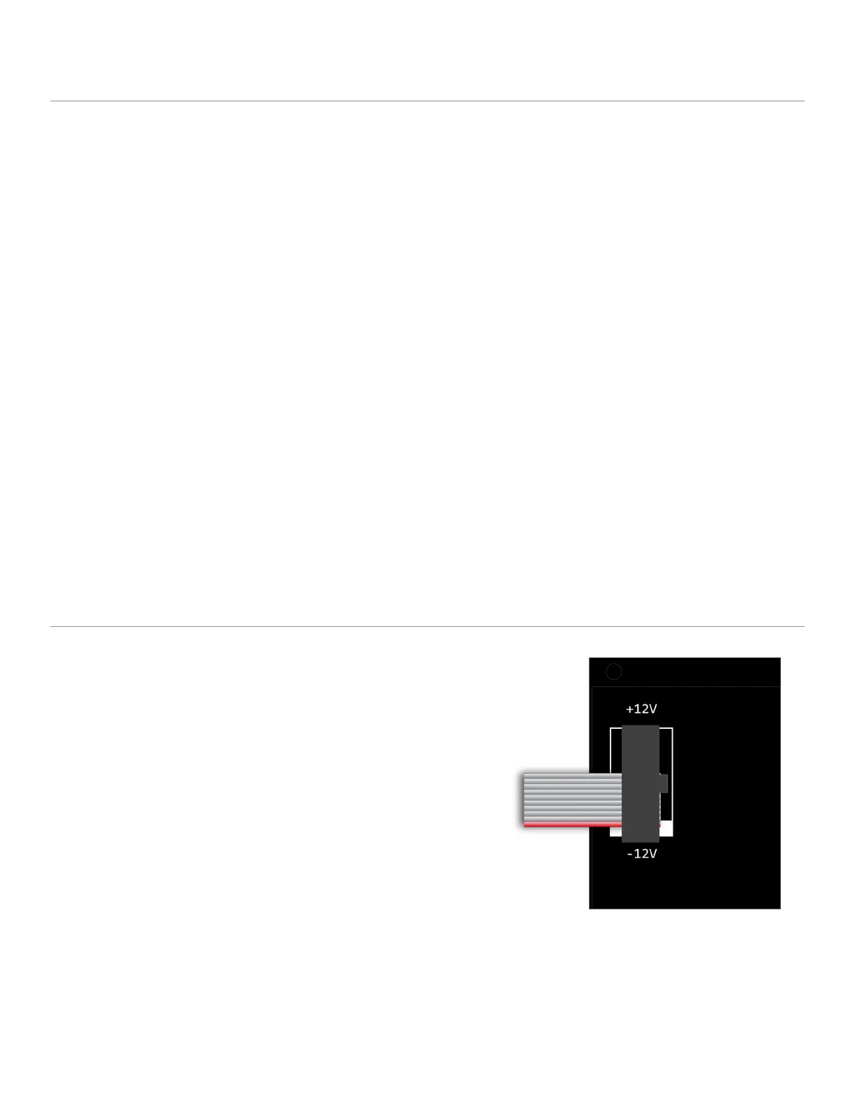
To install, locate 18HP of space in your Eurorack case
and confirm the positive 12 volts and negative 12
volts sides of the power distribution lines.
Plug the connector into your case’s power supply
unit, keeping in mind that the red band corresponds
to negative 12 volts. In most systems, the negative 12
volt supply line is at the bottom.
The power cable should be connected to the module
with the red band facing the bottom of the module.