QUANTECH
FORM QTC3-EG6 (1118)
26
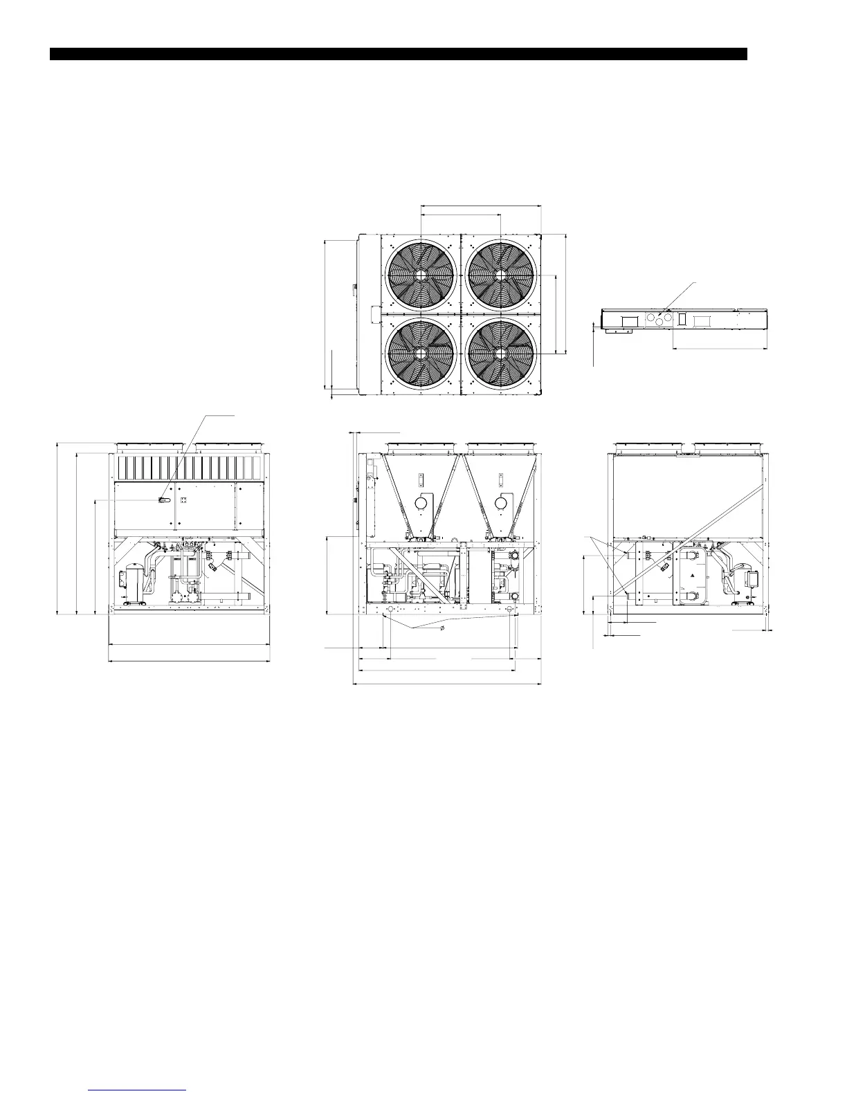
QTC3055THE, QTC3060THE, QTC3079THE
Unit Dimensions
NOTE:
Placement on a level surface of free of obstructions (including snow, for winter operation) or air circulation ensures rated performance, reli-
able operation, and ease of maintenance. Site restrictions may compromise minimum clearances indicated below, resulting in unpredictable
airow patterns and possible diminished performance. The unit controls will optimize operation without nuisance high-pressure safety cut-
outs; however, the system designer must consider potential performance degradation. Access to the unit control center assumes the unit is
no higher than on spring isolators. Recommended minimum clearances: Side to wall – 6'; rear to wall – 6'; control panel to end wall – 4'0'';
top – no obstructions allowed; distance between adjacent units – 10'. No more than one adjacent wall may be higher than the unit.
035-24059-001 REV-E
1117 [44.0]
POWER ENTRY
330.2 [13.00] WIDE X 177.8 [7.00] HIGH
CONTROL PANEL BOTTOM DETAIL
1177 [46.4]
1097 [43.2]
1669 [65.7]
201 [0.8]
822 [32.4]
254 [10.0]
1085 [42.7]
1595 [62.8]
2251 [88.6]
OVERALL HEIGHT
FRAME HEIGHT
2077 [81.8]
82 [3.2]
DISCONNECT SWITCH
(OPTIONAL)
51 [2.0]
2242 [88.3]
FRAME WIDTH
OVERALL WIDTH
2254 [88.8]
2627 [103.4]
2180 [85.8]
442 [17.4]442 [17.4]
WATER CONNECTIONS
OVERALL LENGTH
333 [13.1]
1884 [74.2]
16 [5/8”]
MOUNTING
HOLES TYP
MOUNTING
HOLES TYP
MOUNTING
HOLES TYP
WATER CONNECTION
36 [1.4]
36 [1.4]
269 [10.6]
3” VICTAULIC
INLET