Chapter 3 Calibration
HF Series X-ray Generators - Service Manual Revision W
Quantum Medical Imaging, LLC 3-15
2. The system displays the ION CHAMBER Configuration Screen, as shown
in the example below:
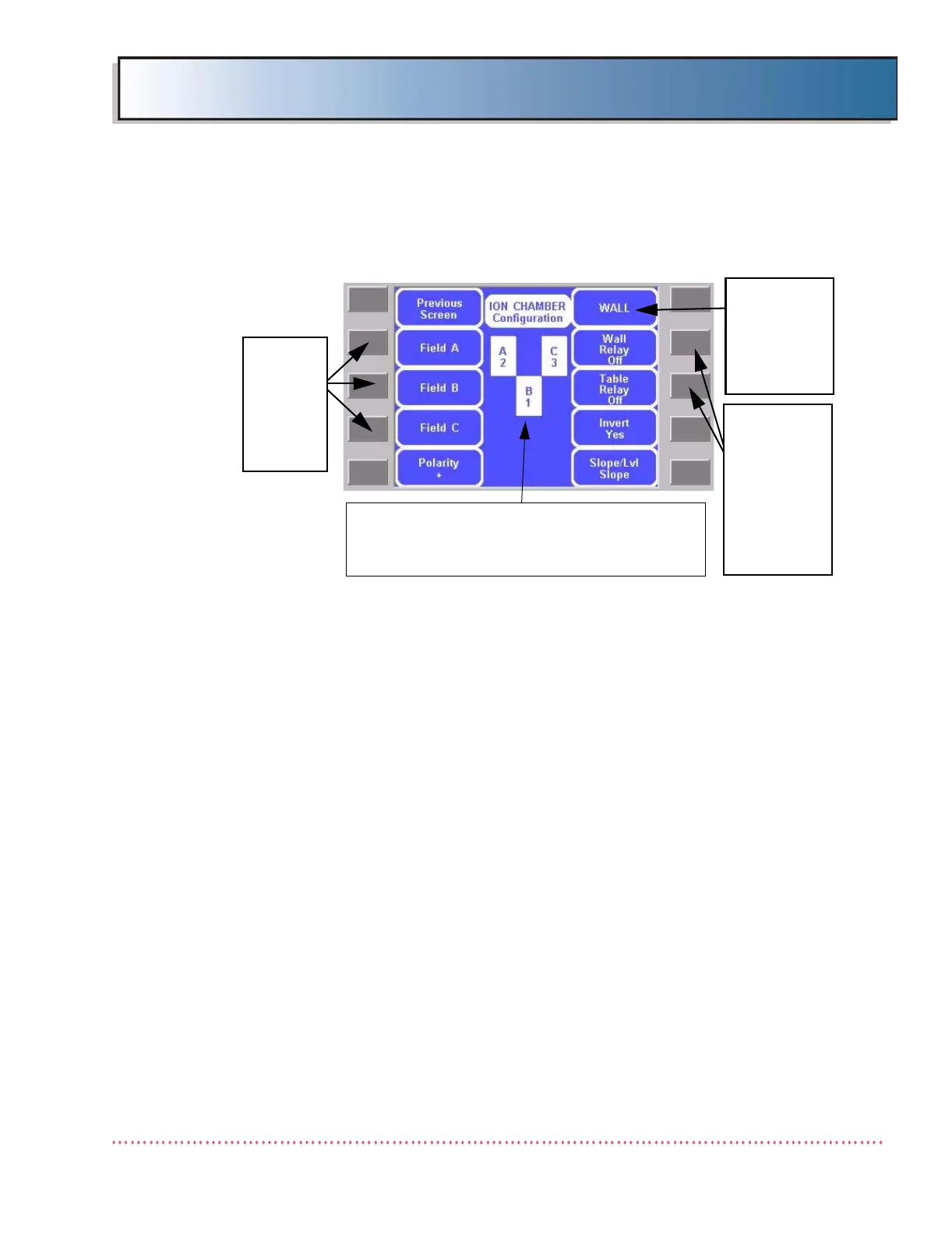
Figure 3-12. ION CHAMBER Configuration Screen
(AID ICX-153 or ICX-1153 Right Hand Load Configuration Shown)
The ION CHAMBER Configuration Screen displays the assignment of ion
chamber detectors (detector A, B, or C) with respect to the generator’s ion
chamber detector select signals (i.e., FIELD SELECT 1, FIELD SELECT 2 and
FIELD SELECT 3) output from AEC Control Board A11 (AY40-031S/
AY40-027S). In other words, assigning "1" to field "A" will enable ion cham-
ber detector "1" when the UPPER LEFT chamber detector field is selected on
the Operator Control Panel (OCP).
The ION CHAMBER Configuration Screen also provides settings that facilitate
proper interfacing of the generator with different ion chamber and receptor
types. These include Polarity, Wall Relay ON/OFF, Table Relay ON/OFF,
Invert, and Slope/Level settings.
PRESS
THESE
KEYS TO
SELECT
ION
CHAMBER
DETECTOR
INDICATES
SELECTED
RECEPTOR
(WALL/TABLE/
WALL 2/
AUXILLIARY)
NOTE: AID ICX-153 or ICX-1153 RIGHT LOAD
USES THIS CONFIGURATION. FOR AID ICX-
153 or ICX-1153 LEFT LOAD, SET A=3 AND C=2.
ACTIVATES
OR DISABLES
WALL/TABLE
RECEPTOR
WHEN
SELECTED
RECEPTOR
KEY IS
PRESSED