QXS-6 Series Specifications 31
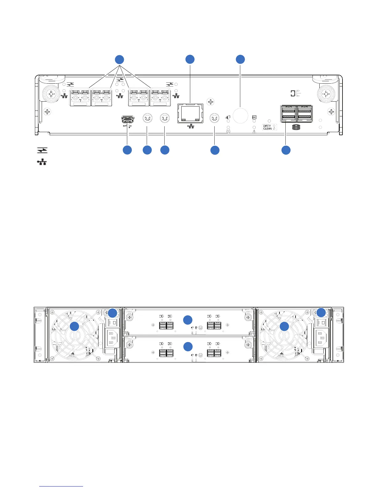
Figure 26 provides the controller I/O module (with ports identified).
Figure 26 Controller I/O Module
48 Drive Expansion Chassis: Rear Panel Components
Figure 27 provides the 48 drive expansion chassis (rear panel components).
Figure 27 Expansion Chassis: Rear Panel Components
CACHE
CLI
CLI
LINK
ACT
S ERVICE−1S ERVICE−2
PORT 0 PORT 1 PORT 2 PORT 3
MGMT
EXP 0 EXP 1
6Gb/s
S
S
A
LINK 0
LINK 1
5
2 3 6 8
1
7
4
= FC LEDs
= 10GbE iSCSI LEDs
1 CNC FC or iSCSI SFP+ Ports (used for host
connection or replication)
2 CLI Port (USB - Type B)
3 Service Port 2 (Service Personnel Use Only) 4 Reserved for future use
5 Network Port 6 Service Port 1 (Service Personnel Use Only)
7 Disabled button (used by engineering only) (Sticker
shown covering the opening)
8 mini-SAS expansion port
S ERVICE
IN
LINK LINK
6Gb/s
S
S
A
6Gb/s
S
S
A
OUT
LINK LINK
6Gb/s
S
S
A
6Gb/s
S
S
A
S ERVICE
IN
LINK LINK
6Gb/s
S
S
A
6Gb/s
S
S
A
OUT
LINK LINK
6Gb/s
S
S
A
6Gb/s
S
S
A
1
1
2
2
3
4
1 Power supplies (AC shown, 2 each) 2 AC Power Switch
3 Expansion I/O Module A 4 Expansion I/O Module B