4.3.1.1 Rotor Replacement (Refer to illustrations below for component identification.)
Tool List
¼” Nut Driver 9/16” Socket and Ratchet Flat Blade Screwdriver
Rubber Mallet 6” Ratchet Extension #2 Phillips Screwdriver
5/64” Hex Wrench 9/16” Wrench
1. Turn off power to the pinspotter. Lock out and tag out the pinspotter in accordance with your bowling
center’s established procedures.
2. Disconnect the motor’s power plug.
3. Remove the motor from the gearbox assembly and move it to a work area.
4. Remove the four long bolts that secure the end bells to the motor frame.
5. Tap the upper end bell with a mallet to free the end bell from the upper rotor bearing.
6. Pull the rotor and lower end bell away from the frame. The rotor will remain attached to the lower end bell
until the next two steps are performed. The upper end bell, while loose, cannot be completely removed
because of the wiring connections. Take care to prevent damaging the motor’s wiring.
7. There is a wave spring that will either remain in the recess on the inside of the upper end bell (if it is, leave
it there) or could have stuck to the upper bearing of the rotor assembly when the rotor was removed. If
the wave spring is on the rotor bearing, remove it and save for reuse.
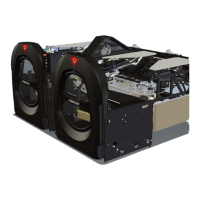
8. Loosen the screw on the lower end bell (see
the illustration at the right) and rotate the
dog away from the rotor assembly’s lower
bearing. Remove the rotor assembly.
9. Remove the key taped to the new rotor
assembly, and insert the shaft of the new
rotor through the opening in the lower end
bell so that the bearing seats within the
recess in the end bell. (You may need to tap
the end bell with the mallet.)
10. Tighten the screw in the lower end bell (refer to the illustration above). Ensure that the dog rotates over
the bearing and stops against the roll pin. Tighten the screw securely.
11. If the wave spring was removed from the recess in the upper end bell, place the wave spring into the
recess in the upper end bell.
 Loading...