GV300 User manual
TRACGV300UM001 - 19 -
Figure 15. Typical Connection with LED
Note:
1. OUT1 will latch the output state during reset.
2. Many modern relays come with a flyback diode pre-installed internal to the relay itself. If the
relay has this diode, insure the proper relay polarity connected is used. If this diode is not internal,
it should be added externally. A common diode such as a 1N4004 will work in most
circumstances.
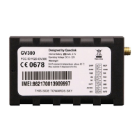
3.12. Device Status LED
Figure 16. GV300 LED on the Case
 Loading...