LTE Module Series
EM05 Hardware Design
EM05_Hardware_Design Confidential / Released 36 / 59
“*” means under development.
3.11.1. W_DISABLE1# Signal
EM05 provides a W_DISABLE1# signal to disable or enable the RF function through hardware operation.
Besides, the RF function can also be enabled or disabled through software AT commands. For more
details, please refer to Chapter 3.4.2.
Table 13: Function of the W_DISABLE1#
3.11.2. LED# Signal
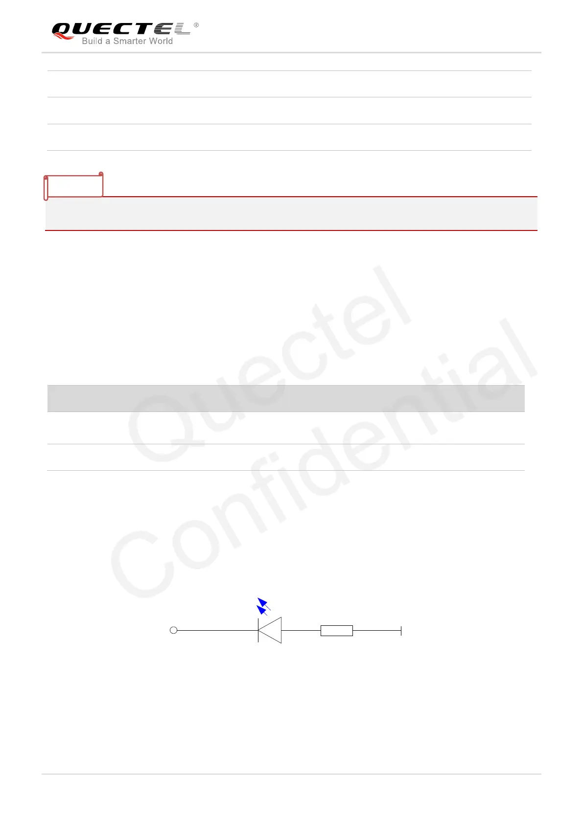
The LED# signal of EM05 is used to indicate the RF status of the module, which can absorb the current
up to 40mA. According to the following circuit, in order to reduce the current of the LED, a resistor must be
placed in series with the LED. The LED is emitting light when the LED# output signal is active low.
Figure 23: LED# Signal Reference Circuit Diagram
The following table shows the RF status indications of the LED# signal.
RF function is determined by software AT commands.
Default: enabled.

 Loading...


