LTE Module Series
EM05 Hardware Design
EM05_Hardware_Design Confidential / Released 35 / 59
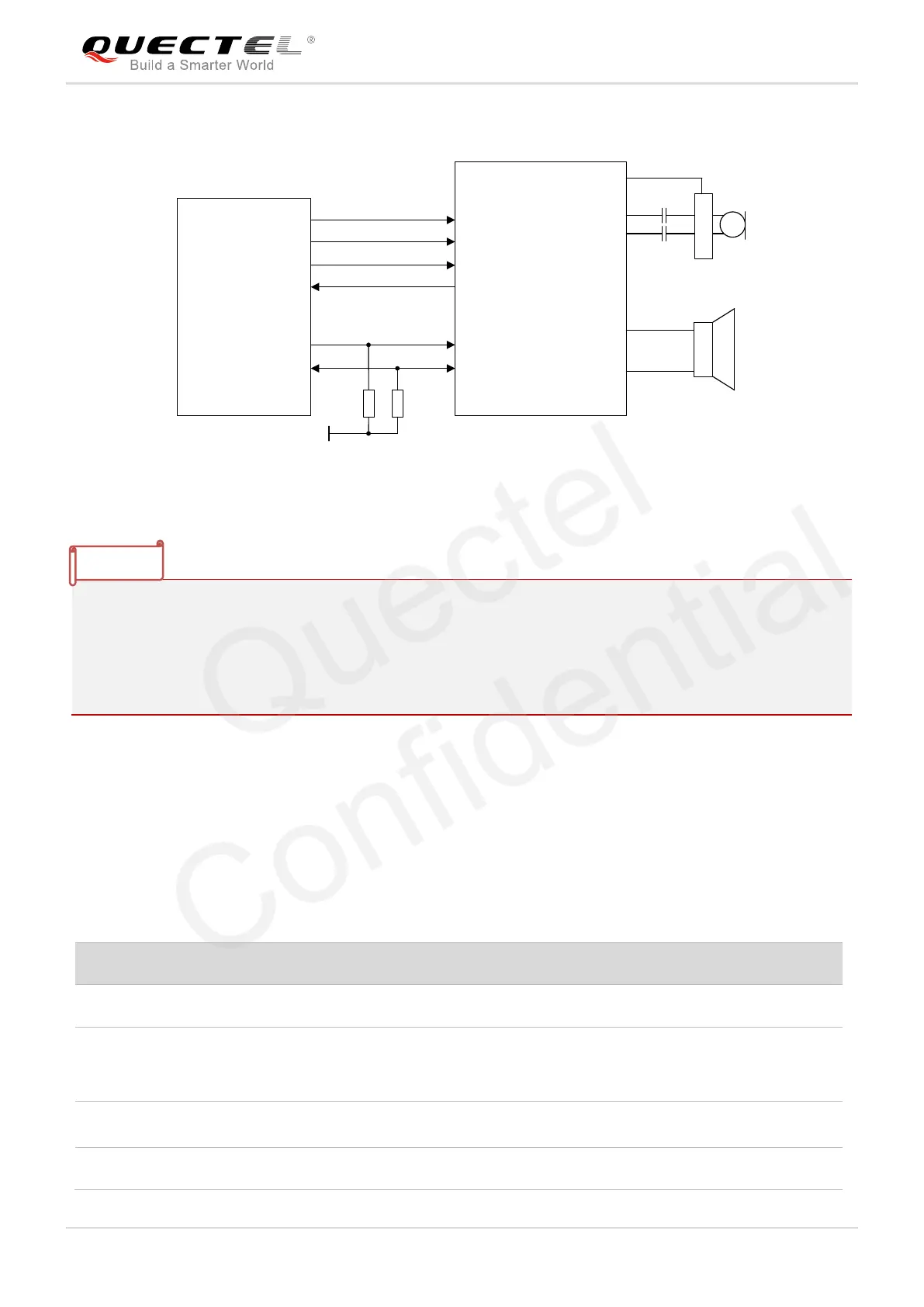
The following figure shows a reference design of PCM interface with external codec IC.
PCM_IN
PCM_OUT
PCM_SYNC
PCM_CLK
I2C_SCL
I2C_SDA
Module
1.8V
NM
BCLK
LRCK
DAC
ADC
SCL
SDA
BIAS
MICBIAS
INP
INN
LOUTP
LOUTN
Codec
NM
Figure 22: Reference Circuit of PCM Application with Audio Codec
1. “*” means under development.
2. It is recommended to reserve a RC (R=22Ω, C=22pF) circuit on the PCM lines, especially for
PCM_CLK.
3. EM05 works as a master device pertaining to I2C interface.
4. EM05-CML does not support I2C interface.
3.11. Control and Indicator Signals
The following table shows the pin definition of control and indicator signals.
Table 12: Pin Definition of Control and Indicator Signals
Airplane mode control. Active low.
It is an open drain and active low signal.
It is used to indicate the RF status of the
module.
A signal to wake up the host.
It is open drain and active low.

 Loading...


