M12 Hardware Design
M12_Hardware_Design_V3.3 - 55 -
Table 16: Pin definition of the ADC
Analog to digital converter.
Analog to digital converter
Table 17: Characteristics of the ADC
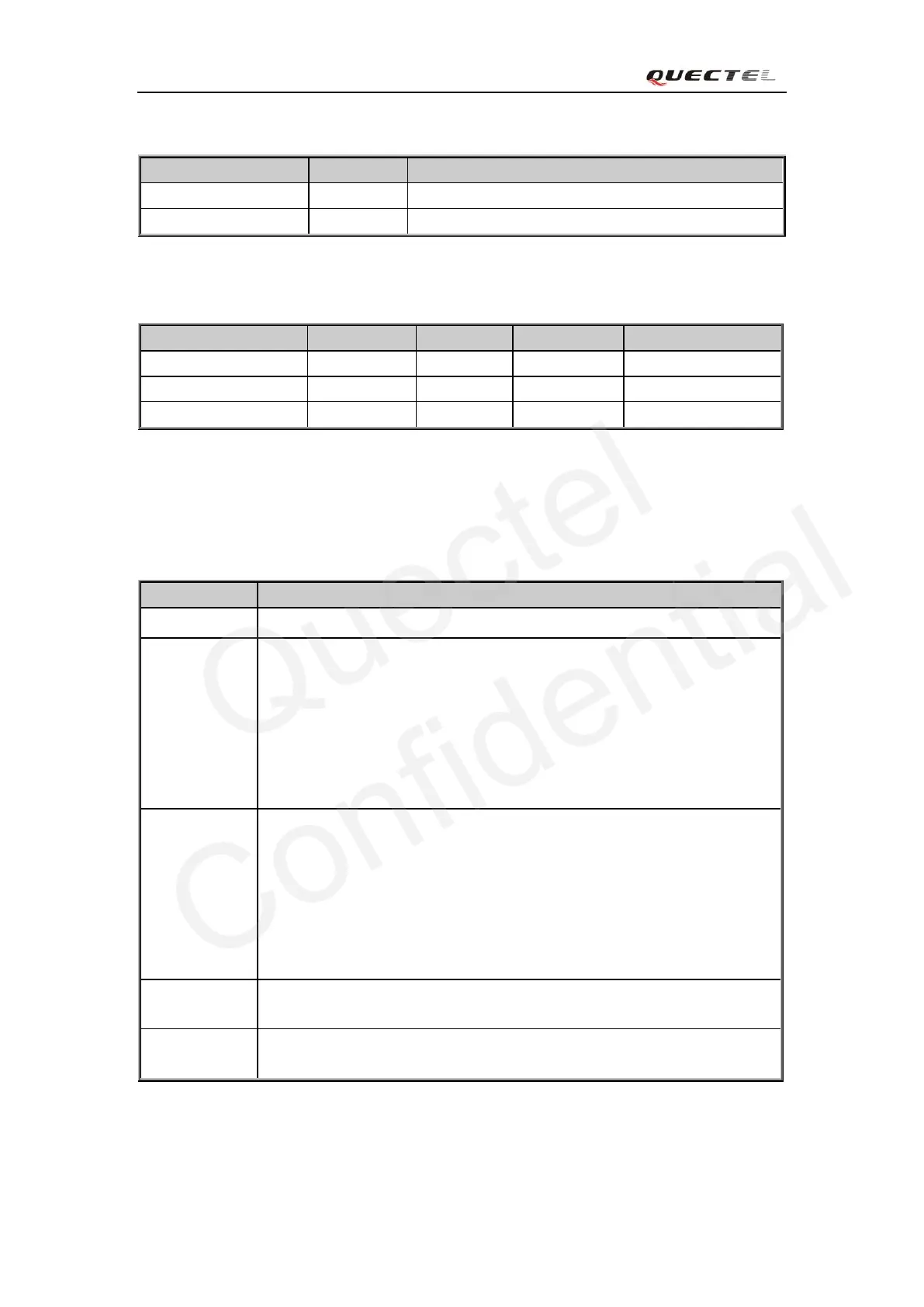
3.12. Behaviors of the RI
Table 18: Behaviors of the RI
Changed to LOW, then:
1. Changed to HIGH when call is established.
2. Use ATH to hang up the call, RI changes to HIGH.
3. Calling part hangs up, RI changes to HIGH first, and changes to LOW
for 120ms indicating “NO CARRIER” as an URC, then changes to
HIGH again.
4. Changed to HIGH when SMS is received.
Changed to LOW, then:
1. Changed to HIGH when data connection is established.
2. Use ATH to hang up the data calling, RI changes to HIGH.
3. Calling part hangs up, RI changes to HIGH first, and changes to LOW
for 120ms indicating “NO CARRIER” as an URC, then changes to
HIGH again.
4. Changed to HIGH when SMS is received.
When a new SMS comes, the RI changes to LOW and holds low level for
about 120 ms, then changes to HIGH.
Certain URC can trigger 120ms low level on RI. For more details, please
refer to the document [10]
If the module is used as a caller, the RI would maintain high except the URC or SMS is received.
On the other hand, when it is used as a receiver, the timing of the RI is shown below: